
Instruction manual

Appendix D – Adding or Replacing I/O Boards
148
Optima Instruction Manual
Removing I/O Boards
To remove an Optima I/O board (or blank board plate):
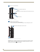
Note: If the screw circled in red in Step 1 is silver or if a silver screw was shipped with the new
board(s), be sure to screw it into the same hole in Step 6 of the “Adding I/O Boards” procedure on
page 153.
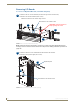
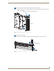
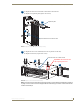
FIG. 89 Remove 5 screws and rack ear (4 screws)
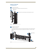
FIG. 90 Remove 3 screws and expansion plate (2 screws)
Screw will be in one of these 2 holes
1a: Remove the five screws indicated (four from the top and one from the side).
1b: Remove the rack ear indicated (four screws).
Stand the enclosure on this side for Steps 2 and 3.
1
1a
1a
1b
Important: See Note below this
step regarding this screw.
2a: Remove the three screws indicated from the bottom of the enclosure.
2b: Remove the expansion plate (two screws).
Expansion plate
Screw will be in one of these 2 holes
2
2a
2b