
Instruction manual


Installation and Setup
33
Optima Instruction Manual
Attaching Remote XNNet Control Devices
A remote XNNet control device is any device that sends and receives XNNet protocol over the Remote
port. AMX AutoPatch XNNet control devices include remote control panels (e.g., the CP-15 and
CP-20A), as well as Single Bus Controllers (SBCs) and Preset SBCs.
The instructions below are for attaching a device to the Remote port, which is located on the CPU board
(3 RU enclosures) or on the XNNet Expansion board (2 RU enclosures). For specific product
information, see the individual device’s documentation.
Communication Cable Requirements
A two-conductor, 20 AWG, 7/28 strand cable with a drain wire or shield, such as Alpha 2412C
(customer supplied)
Maximum length of cable: 1,000 ft. (305 m) total, including linked panels
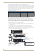
To establish a Remote port connection with an XNNet device:
1.
Attach one end of the XNNet link cable to the corresponding port on the device (see the individual
product documentation).
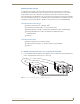
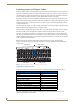
2. On the Optima’s CPU, unplug the Remote connector.
3. Loosen the screws on the Remote connector.
4. Insert the two wires of the XNNet link cable from the device into the Remote connector leaving the
center slot empty (FIG. 15).
Note that either wire can be inserted into either of the outer slots.
5. Tighten both screws and plug the connector back into the CPU.
6. If not already on, apply power first to the Optima enclosure before applying power to the XNNet
device (see “Applying Power and Startup,” page 35).
7. Execute a switch to ensure the Optima is working properly (see “Executing a Test Switch,”
page 38).
FIG. 15 Insert wires into XNNet connector on the CPU