
Instruction manual
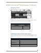


Stereo Audio I/O Boards
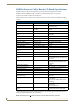
89
Optima Instruction Manual
Attaching Wires
When attaching stereo audio input and output wires, refer to the sheet labeled “AutoPatch Connector
Guide” that ships with the system. The sheet shows where to attach the wires on the rear of each
enclosure. Follow the sheet exactly; the system was programmed at the factory to operate only as
indicated on the sheet. For multiple-enclosure systems, each enclosure will be numbered (e.g., “Chassis
1 of 3”) on a label located on the left side near the power receptacle.
Signals may only be routed from the inputs on a board to the outputs on the same board because each
board has its own switching matrix.
To attach stereo audio input and output wires:
1.
Unscrew the clamps on the audio connector.
2. Insert the wires (FIG. 51) for wire placement for balanced and unbalanced audio) and firmly
re-tighten the clamps to make proper connections.
Note: For stereo audio signals using twisted pair wire, connect the shield (ground) only at one end
(recommend receiving end) to minimize low frequency noise.
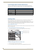
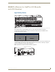
Wiring Sources and Destinations
Source and destination devices will require either balanced (differential) or unbalanced (single-ended)
connections. FIG. 52 illustrates the options for wiring between the sources and the input connectors and
between the output connectors and the destinations. More than one of these options can be used in the
same system. For balanced and unbalanced wiring details, see FIG. 51.
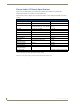
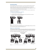
FIG. 51 Balanced and unbalanced stereo audio wiring
FIG. 52 Options for source-to-Optima-to-destination 5-term wiring
Balanced audio
Unbalanced audio
Optima Stereo Audio
5-Term Wiring
Source balanced
– wired balanced
Source balanced
– wired unbalanced
Source unbalanced
– wired unbalanced
Destination balanced
– wired balanced
Destination balanced
– wired unbalanced
Destination unbalanced
– wired unbalanced
Grey = Ground
Input Connectors
Output Connectors