Instruction Manual Precis DSP Distribution Matrix AutoPatch Matrix Switchers Release: 7/06/2009 Firmware: v1.2.
AMX Limited Warranty and Disclaimer All products returned to AMX require a Return Material Authorization (RMA) number. The RMA number is obtained from the AMX RMA Department. The RMA number must be clearly marked on the outside of each box. The RMA is valid for a 30-day period. After the 30-day period the RMA will be cancelled. Any shipments received not consistent with the RMA, or after the RMA is cancelled, will be refused. AMX is not responsible for products returned without a valid RMA number.
Software License and Warranty Agreement • LICENSE GRANT. AMX grants to Licensee the non-exclusive right to use the AMX Software in the manner described in this License. The AMX Software is licensed, not sold. This license does not grant Licensee the right to create derivative works of the AMX Software. The AMX Software consists of generally available programming and development software, product documentation, sample applications, tools and utilities, and miscellaneous technical information.
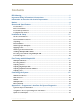
Contents Contents ESD Warning .......................................................................................................1 Important Safety Information & Instructions .......................................................2 Information et directives de sécurité importantes...............................................3 Notices ................................................................................................................4 Overview & Specifications .............................
Contents ii Precis DSP Instruction Manual
ESD Warning ESD Warning To avoid ESD (Electrostatic Discharge) damage to sensitive components, make sure you are properly grounded before touching any internal materials. When working with any equipment manufactured with electronic devices, proper ESD grounding procedures must be followed to ensure people, products, and tools are as free of static charges as possible. Grounding straps, conductive smocks, and conductive work mats are specifically designed for this purpose.
Important Safety Information & Instructions Important Safety Information & Instructions When using and installing your AMX AutoPatch product, adhere to the following basic safety precautions. For more information about operating, installing, or servicing your AMX AutoPatch product, see your product documentation. Read and understand all instructions before using and installing AMX AutoPatch products. Use the correct voltage range for your AMX AutoPatch product.
Information et directives de sécurité importantes Information et directives de sécurité importantes Veuillez vous conformer aux directives de sécurité ci-dessous lorsque vous installez et utilisez votre appareil AMX AutoPatch. Pour de plus amples renseignements au sujet de l’installation, du fonctionnement ou de la réparation de votre appareil AMX AutoPatch, veuillez consulter la documentation accompagnant l’appareil.
Notices Notices Copyright Notice AMX© 2009 (Rev B), all rights reserved. No part of this publication may be reproduced, stored in a retrieval system, or transmitted, in any form or by any means, electronic, mechanical, photocopying, recording, or otherwise, without the prior written permission of AMX.
Notices Lithium Batteries Notice Switzerland requires the following notice for products equipped with lithium batteries. This notice is not applicable for all AMX equipment. Upon shipment of the products to Switzerland, the requirements of the most up-to-date Swiss Ordinance Annex 4.10 of SR 814.013 will be met by providing the necessary documents and annual reports relative to the disposal of the batteries to the Swiss Authorities. Trademark Notices AMX®, AutoPatch®, and NetLinx® are trademarks of AMX.
Notices 6 Precis DSP Instruction Manual
Overview & Specifications Overview & Specifications Applicability Notice Precis DSP Distribution Matrices are available in two configurations: 8x8 and 18x18. Precis DSP Models: FGP37-0808-00P, 8x8 (1 RU) FGP37-1818-00P, 18x18 (2 RU) In addition to being a stereo audio router, this product supports Digital Signal Processing (DSP) for the following audio features: volume, tone, balance, 10-band graphic equalization, and input gain.
Overview & Specifications Enclosure Hardware Power indicator Power receptacle Power switch Input connectors Output connectors CONTROL (RS-232) serial port FIG. 1 Front & rear view of model FGP37-1818-00P Enclosure Front Precis DSP models come with a blank front panel and a power indicator in the upper right corner. Enclosure Rear Descriptions follow for the hardware on the rear of a Precis DSP.
Overview & Specifications Precis DSP Specifications Applies to Precis DSP models FGP37-0808-00P and FGP37-1818-00P. Specifications – General Parameter Approvals Value CE, UL, cUL Humidity 0 to 90% non-condensing Operational Temperature 32° F to 95° F (0° C to 35° C) AC Power 100 VAC to 240 VAC single phase, 50 Hz to 60 Hz 1 A @ 115 VAC max. 0.7 A @ 230 VAC max. Power Consumption (max.) 80 Watts Power Consumption (typical) 45 Watts, fully loaded enclosure Thermal Dissipation (max.) 273 BTU/hr.
Overview & Specifications Configuration & Control Configuration Information Precis DSP systems are pre-engineered to switch stereo audio for two configuration sizes (8x8 and 18x18). Control Options Precis DSP systems support two different protocols: BCS (as ASCII characters sent through the RS-232 serial port) and TCP/IP (with external APWeb Server module). Several control options are available for Precis DSP systems. AMX Control Devices The Precis DSP is compatible with a number of AMX control devices.
Installation & Setup Installation & Setup Site Recommendations When placing the enclosure, follow the recommendations and precautions in this section to reduce potential installation and operation hazards. For complete specifications, see the tables on page 9. Choose a clean, dust free, (preferably) air-conditioned location. Avoid areas with direct sunlight, heat sources, or high levels of EMI (Electromagnetic Interference).
Installation & Setup Circuit Overloading When connecting the equipment to the supply circuits, be aware of the effect that overloading the circuits might have on over-current protection and supply wiring. Reliable Earthing (Grounding) Reliable earthing of rack-mounted equipment should be maintained. If not using a direct connection to the branch circuit (e.g., plugging into a power strip), pay particular attention to supply connections.
Installation & Setup Rack Installation Precis DSP Distribution Matrix enclosures fit in a standard EIA 19 in. (48.26 cm) rack. Rack ears are provided. Required items for rack installation: Enclosure Rack ears & screws Standard EIA 19 in. (48.26 cm) rack Screwdriver Screws that fit your rack for mounting the enclosure Power cord Surge-protector – highly recommended PC or laptop computer with a null modem cable (for communication with the Precis DSP via the RS-232 port, i.e.
Installation & Setup To install and set up a Precis DSP in a rack: 1. On the side of the Precis DSP, remove the bottom two screws closest to the front panel (FIG. 3). Align the holes on one of the rack ears with the empty holes on the side of the enclosure and replace the screws (three screws for the 1 RU; four screws for the 2 RU). Repeat for the other rack ear. Front Panel 2 RU Front Panel 1 RU Insert Insert Remove & then replace Remove & then replace FIG.
Installation & Setup Attaching Inputs & Outputs Input and output connectors are the attachment points for source and destination devices that connect to the system. Viewed from the rear of a Precis DSP enclosure, the inputs (for sources) are on the left side of the enclosure, and the outputs (for destinations) are on the right side. Precis DSP models have gold-plated RCA connectors for routing stereo audio.
Installation & Setup Applying Power The enclosure’s universal power receptacle will accept all major international standard power sources. A standard US power cord is provided for installations within the US. Maximum power specifications are on the power receptacle (also listed on page 9). Always use an earth-grounded power cord / system with a Precis DSP. The source electrical outlet should be installed near the Precis DSP, easily accessible, and properly grounded.
Installation & Setup Attaching an External Controller The Precis DSP can be controlled externally by attaching an external control device/system that uses one of the communication protocols listed below: BCS (Serial) – ASCII sent over a null modem serial cable via the CONTROL (RS-232) port XNNet – AMX AutoPatch protocol via the CONTROL (RS-232) port TCP/IP – requires an external module; see the APWeb Server module documentation An external serial controller is any device that can send and receive ASCII cod
Installation & Setup Serial Port Setting Table for Precis DSP 3. Plug the other end of the serial cable into the serial port on the PC (or other serial controller/device). 4. Open the serial communication software and set the port settings to match the Precis DSP default settings (see table to the right). The settings on the PC serial communication software and the enclosure must correspond to each other. If a change is required to make them match, change the PC’s settings.
Installation & Setup 3. From the Comm menu, select Connect. 4. From the Options menu, select Rediscover VMs. If the system discovery fails again, contact technical support (see page 20). Executing a Test Switch Using APGraphic EQ Execute a test switch to verify the system is working properly before attaching all inputs and outputs. Before executing the test switch, make sure the first two source devices and the first two destination devices are connected to the input and output connectors.
Installation & Setup Troubleshooting If the test switch did not execute correctly: Check the power indicator on the front of the enclosure. If it is not illuminated, check the power cords. Check all signal connections on the rear of the enclosure(s) to make sure everything is physically set up correctly. Check all power switches on the source and destination devices to make sure they are all turned on. Attempt the switch again. If the switch still does not work, contact technical support (see below).
Fine-Tuning with APGraphic EQ Fine-Tuning with APGraphic EQ Overview APGraphic EQ software is used for system setup and adjusting audio functionality.* The software is found on the AMX AutoPatch CD that ships with the Precis DSP. For more information, see the Release Notes and the Readme file.
Fine-Tuning with APGraphic EQ Executing Switches Before fine-tuning the system for its final location, route a few switches to check that the system is working properly and to determine what adjustments are needed. This section provides basic information for executing switches using the CrossBar. For complete control information using APGraphic EG, see page 28. To execute switches with the APGraphic EQ CrossBar: 1. Open APGraphic EQ (see page 18). 2. From the Options menu, select Show > CrossBar View.
Fine-Tuning with APGraphic EQ Adjusting Digital Input Gain Inputs are set to unity gain at the factory and have a gain adjustment range of -10 dB to +10 dB. Input gain adjustments should be made before the outputs are fine-tuned. Inputs cannot be muted. Purpose & Application of Input Gain Adjustment Adjusting input gain (the nominal level of the signal from the source device) allows source signals of varying amplitudes to be equalized before they are routed and the volume is adjusted.
Fine-Tuning with APGraphic EQ Adjusting Equalization Bands & Balance Precis DSP models provide a 10-band graphic equalizer to boost or cut the various frequencies (bands) for each output. Each equalization band spans one octave and is identified by its center frequency. The bands are set for a flat response (0 dB) at the factory. The adjustment range for each band is -12 dB to +12 dB. Balance is normally adjusted as part of system setup and fine-tuning but can also be adjusted any time during operation.
Fine-Tuning with APGraphic EQ Adjusting Tone Tone is normally adjusted along with balance and volume as part of system setup and fine-tuning but can be adjusted any time during operation. Note: The button immediately left of the Reset button is used to toggle between the Tone and EQ sliders. When the EQ sliders are visible, the button says Tone; when the Tone sliders are visible, the button says EQ. To adjust tone for an output: 1. Using the CrossBar, route an input to the output needing adjustment. 2.
Fine-Tuning with APGraphic EQ 26 Precis DSP Instruction Manual
Controlling the System Controlling the System Control Options After the initial setup (in which APGraphic EQ is used for test switches, volume control, and fine turning), the Precis DSP can be controlled using any of the following: AMX Control Devices APControl 3.0 APWeb (TCP/IP control via an external module) APGraphic EQ BCS Commands Third-party Controllers (for operating instructions, see controller documentation) AMX Control Devices The Precis DSP is compatible with a number of AMX control devices.
Controlling the System APWeb APWeb requires an external module. For installation directions, see the Quick Start Guide that ships with the APWeb Module. For directions on executing and disconnecting switches using APWeb, see the APWeb documentation on the AMX AutoPatch CD or at www.amx.com. APGraphic EQ The APGraphic EQ has a CrossBar (interface with crosspoints for switching) that can be used for ongoing control after the system is set up and fine tuned.
Controlling the System Customizing the CrossBar The CrossBar can be customized to reflect your individual system and preferences. Icons and custom channel names can be added to the Input and Output buttons (font size and icon size are also adjustable). The background color of the CrossBar can be customized using the Window Color dialog box. Customized settings are automatically saved. To add icons and custom names to input and output buttons: 1.
Controlling the System BCS Commands Precis DSP models can be controlled by entering BCS (Basic Control Structure) commands into a terminal emulation program (e.g., HyperTerminal). BCS command equivalents for all DSP functionality adjustments are provided for advanced users and programmers who wish to create their own control programs; see the BCS Protocol Instruction Manual on the AMX AutoPatch CD or at www.amx.com.
Controlling the System Executing a Test Switch with BCS The following test switch routes Input 2 to Output 1 (the level does not need to be specified since the Precis DSP only switches audio). To execute a test switch using BCS commands: 1. Enter the following BCS command line: CI2O1T When the “T” appears, the system has successfully executed the command. If any other characters appear, the command was not successful. Verify that the source signal is audible at the destination.
Controlling the System 32 Precis DSP Instruction Manual
Appendix A – Programmer’s Interface for System Diagnostics Appendix A – Programmer’s Interface for System Diagnostics System Component Information The Precis DSP displays system information in its splash screen* for diagnostic purposes. The information indicates the current status and well-being of the system components.
Appendix A – Programmer’s Interface for System Diagnostics Verbosity Settings The verbosity (v) settings (v0, v1, v2, v3) correspond to the level of detail that will be displayed, with v0 being the lowest level of detail and v3 being the highest level. Component Settings Detailed information for a single system component can be specified by using its identity (i) number setting (i1 through i5) in the following table.
Appendix A – Programmer’s Interface for System Diagnostics Splash Screen Examples Following are four examples of splash screen information that could be displayed when different verbosity/component settings are specified. Depending on the amount of detail provided, you may need to scroll to see the entire display. Use the first example to check the host software (IOS) version and the hardware driver (appcode) version. ~scrv3i1! [1:Enclosure] Precis DSP [host software] v3.4.2 [hardware driver] v1.2.
Appendix A – Programmer’s Interface for System Diagnostics ~scrv3i4! [4:Hardware Boards] detected [io boards] count = 1 [board 1] e000 [hardware function checks] none FIG. 12 Display for v3i4 (verbosity 3, component 4) ~scrv3i5! [5:VM Configuration] count = 2 [VM 0] ‘All’ 8x8x1 [VM 2] ‘A2’ 8x8x1 [VM 0 master] 0x0 0 0 1 (self) [VM 2 master] 0x0 0 0 1 (self) FIG.
AMX. All rights reserved. AMX and the AMX logo are registered trademarks of AMX. AMX reserves the right to alter specifications without notice at any time. ©2009 07/09 It’s Your World - Take Control™ 3000 RESEARCH DRIVE, RICHARDSON, TX 75082 USA • 800.222.0193 • 469.624.8000 • 469-624-7153 fax • 800.932.6993 technical support • www.amx.