Document Edition Part Number Date First 907-569-01 June 1996 VTEL, the VTEL logo, Communication Without Boundaries, EnterpriseSeries, Leadership Conferencing, Team Conferencing, MediaConferencing, AppsView, PenPal for Windows, SmartCam, and CommandTouch are trademarks of VTEL Corporation. Windows is a registered trademark of Microsoft Corporation. All other brand names and product names are trademarks or registered trademarks of their respective companies. © 1995, 1996 by VTEL Corporation.
Terminology ............................................................................................................................... 1 Touch Panel Characteristics ....................................................................................................... 2 Menus Section ...........................................................................................................................
!#! % ! '# ( Making a On-Hook Telephone Call ........................................................................................12 Dialing When the Phone is Off-Hook ..................................................................................... 12 Answering a Telephone Call ...................................................................................................13 Hanging Up a Telephone Call .....................................................
' ( + ON/OFF Button ................................................................................................................... 20 SIZE Button (TC Systems Only)............................................................................... 21 MOVE Button (TC Systems Only) ........................................................................... 21 ON/OFF Button (TC Systems Only) .......................................................................
# "! Send Local Camera Section..................................................................................................... 28 Slides Section .......................................................................................................................... 28 PRINT SLIDE Button ............................................................................................... 29 SAVE SLIDE Button ........................................................................
COMPARE DEVICE Button ................................................................................. A-3 SHOW DEVICE Button ......................................................................................... A-3 Serial Number ......................................................................................................... A-3 AXLINK Button ..................................................................................................... A-3 FIRMWARE REVISION Button .....
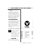
Introduction VTEL ™ CommandTouch ™ is the latest in video conferencing controllers. This “touch to operate” panel allows you to control the EnterpriseSeries ™ Team Conferencing ™ System (TC) and Leadership Conferencing ™ System (LC) features in a simple, straightforward manner. Since it can be modified to control other devices, CommandTouch can provide total control for all your video conferencing and room requirements.
System Start-up And Touch Panel Operatio During the EnterpriseSeries TC or LC power-up sequence, system status information is displayed on the main video monitor. During this time, do not attempt to use the CommandTouch panel. When the TC or LC Systems’ beginning VTEL logo page is displayed on the monitor, the CommandTouch panel functions can be activated . The CommandTouch panel is a touchsensitive device.
and LC functions through five major touch screen menus. The five major menus are: • MAIN (default menu at power-on • LOCAL CAMERA • REMOTE CAMERA • SLIDES • VCR Any major menu may be accessed from any other major menu by touching its button on the Menus section of the screen. When a menu is selected, its button stays illuminated. A complete description of the five major menus and their associated secondary pages follows this section.
Some CommandTouch functions are available on many pages : • Online HELP butto • MORE butto • DONE butto • AUDIO Sectio The touch panel provides online help for most functions. The HELP button is located in the lower-left corner of the page, in the Menus section. When you press the HELP button, a scrolling Help page appear s. Press the DONE button to leave the Help page and return to normal operati on.
The DONE button is located in the lowerright corner of secondary pages. Pressing this button returns you to the previous page or menu. In some cases, it terminates the current operatio n . Buttons that control local audio are located in the upper-right corner of most of the touch panel pages and menus. Press the INCREASE button (at top) to increase audio volume.
Touch panel buttons provide access to system features, indicate current system status, and provide visual responses to users’ input. Four button states are possible. Momentary The button illuminates while it is being touched. For example, when adjusting a camera’s iris setting, the OPEN button illuminates while it is pressed, indicating that the control is responding to touch. The button dims when released.
Setting Flash The button flashes twice when pressed and held. This changes the setting for that feature. For example, when a camera preset is stored, the setting flash provides positive feedback to the user that the operation has been carried out. Touching one button can sometimes affect another button’s status.
MAIN Menu The MAIN menu’s functions are associated with establishing and closing video conferences. To establish a video conference connection, use the Video Conference Call Control section of the MAIN menu. You can press either of the following buttons to connect to another site: • SPEED-DIAL button (See SPEED-DIA menu on page 9. • HAND-DIALER button (See HANDDIALER menu on page 11.
SPEED-DIAL Menu Use the SPEED-DIAL button to access the SPEED-DIAL menu. From the SPEED-DIAL menu, you can also access the HAND-DIALER menu to manually dial a site. On LC systems you can also access the TELEPHONE menu to add an audio-only caller to a conference cal l. You must use the Address Book facility in AppsView to enter addresses that will then be available for your use in the CommandTouch SPEED-DIAL list (the scrollable list on the left side of the SPEED-DIAL menu).
Note: You can substitute another entry onto an existing SPEED-DIAL SITE button by following Steps 1–3 above. SPEED-DIAL SITE buttons Dialing with the SPEED-DIAL Menu There are two dialing methods that you can use in the SPEED-DIAL menu. • Speed Dial with the SPEED-DIAL SITE button. (See previous page for SPEEDDIAL SITE button setup instructions.) • Dial from the SPEED-DIAL List.
HAND-DIALER Menu Use the HAND-DIALER button to access the HAND-DIALER menu. This screen allows you to dial a site manually. Select a Line Speed Select a line speed before dialing by using the scrollable list in the middle of the menu. If you are making a dual port call, select a dual port line option such as 2x56. In dual port calls, both the Port A and Port B lines will be selected at the same time.
TELEPHONE Menu (LC Systems Only) If your LC is connected to a telephone line, you can make and answer telephone calls during a videoconference. Use the TELEPHONE button to access the TELEPHONE menu. This screen allows you to use the voice telephone in a conference call. Making a On-Hook Telephone Call To enter a telephone number, touch the numbered keys on the telephone keypad. Press the DIAL button to initiate your call.
Answering a Telephone Call If someone calls when you are in a videoconference and your system administrator has set the system’s Auto Answer option to Off, the Telephone window opens in AppsView. Press the ANSWER button to add the caller into the conference. If someone calls and the Auto Answer Option is set to On, the Telephone window opens and Appsview answers the call automatically.
MAIN Menu - More Page Pressing the MORE button in the MAIN menu activates a secondary page which contains the CommandTouch Configuration section. SETUP Butto Pressing the SETUP button activates the touch panel’s Setup page. The Setup page allows you to do some simple customization of the touch panel. See Appendix A for more detailed information on the Setup page. Press the EXIT button, located in the upper-right corner, to return to the previous page.
LOCAL CAMERA Menu The LOCAL CAMERA menu contains the local camera selections, presets, zoom, focus and iris functions. There are three local camera sources on the LC and four camera sources on the TC which can be transmitted to remote sites. Use the Send Local Camera section’s buttons to choose the video source you wish to transmit. When you select a local camera, its button remains illuminated until another local camera, the PC, or a local preset is selected.
VIDEO MUTE Button (TC Systems Only To suspend local video transmission to the remote site, touch the VIDEO MUTE button. The VIDEO MUTE button flashes when activated. Activating the video mute feature also mutes the local microphone. The LOCAL CAMERA PRESETS button automatically selects a certain camera or adjusts a camera to a previously stored position, including its associated zoom, iris and focus refinements.
WIDE ANGLE PRESET Butto You can use this larger button to designate and quickly recognize and recall a preset for a wide-angle view of the entire room. You may use these buttons to control the pan, tilt, and zoom adjustments of the selected local camera. The Camera Control buttons are used only with cameras which support pan, tilt, and zoom operations. MOVE Butto The MOVE arrow buttons move the view of the selected camera in the direction of the arrows.
FOCUS Butto The FOCUS buttons control the image sharpness. ZOOM Button The ZOOM buttons control the overall field of view . The Audio section appears as part of the LOCAL CAMERA menu. The buttons in this section control the volume and muting functions as described in detail on page 5.
# The View section’s buttons are used to select what you see on your local video monitor. The choices are viewing the PC desktop, PenPal for Windows, or the PIP window. Touch this button to display the current local PC desktop. PenPal for Windows Butto Press this button to view the PenPal for Windows application. Refer to your system User’s Handbook for detailed information about PenPal for Windows.
Picture In Picture Control (PIP) The PIP function allows you to view two separate video displays at the same time on a single video monitor. By default on a two-monitor system, the PIP window displays the video you are sending to the remote site. The monitor displays the remote video source. By default on a onemonitor system the PIP window displays the video you are sending to the remote site.
SIZE Button (TC Systems Only) When you press the SIZE button, you can shrink or enlarge the PIP window. MOVE Button (TC Systems Only) When you press the MOVE button, you can move the smaller PIP window within the larger screen image. ON/OFF Button (TC Systems Only) When you press the ON/OFF button, you can toggle the PIP window to appear and disappear.
REMOTE CAMERA Menu The REMOTE CAMERA menu provides control of the remote site’s cameras. Most of the sections and buttons in this menu provide the same control over the remote site’s cameras as for the local cameras. # $ Select which remote camera you wish to view by pressing its associated button. When you select a camera, the button is not illuminated when a remote camera or a remote preset is selected.
$ A preset button automatically selects a certain camera or moves a camera to a previously stored position, including associated zoom and focus refinements. A call must be established to set a preset for a remote camera. To select a preset, press and release the desired preset button. To store a preset, select the desired camera. Use the camera controls to select the view, including zoom and focus adjustments if the camera supports pan, tilt, and zoom functions.
MOVE Button The MOVE arrow buttons move the view of the selected camera in the direction of the arrows. FOCUS Button The FOCUS buttons control the image sharpness. ZOOM Button The ZOOM buttons control the field of view.
The Audio section appears as part of the REMOTE CAMERA menu. The buttons in this section control the volume and muting functions as described in detail on page 5. The Audio buttons on this menu are used to control only the local volume level and to mute the local microphones. # The View section’s buttons are used to select what the remote site sees on its video monitor. The choices are Windows applications, PenPal for Windows, or the PIP window.
Picture In Picture Control (PIP) Note: This facility controls the PIP window on the Local Site only. You do not have control over the Remote Site’s PIP window. The PIP function allows you to view two separate video displays at the same time on a single video monitor. By default on a two-monitor system, the PIP window displays the video you are sending to the remote site. The monitor displays the remote video source.
TC PIP Interface On TC systems, when you press the PIP ON/OFF button, a different set of PIP buttons appears. The PIP buttons for the TC are described next. SIZE Button (TC Systems Only) When you press the SIZE button, you can shrink or enlarge the smaller PIP window. MOVE Button (TC Systems Only) When you press the MOVE button, you can move the smaller PIP window within the larger screen image.
SLIDES Menu The SLIDES menu provides access to the TC and LC graphics functions, such as printing, saving, and sending slides. On LC systems, the CAMERA 4 and VIDEO MUTE buttons on the Send Local Camera Section do not appear on the touch panel . The Send Local Camera section appears as part of the SLIDES menu. The buttons in this section are used to select the local video source that is transmitted to the remote site.
$% % Pressing the CommandTouch PRINT SLIDE button prints the slide currently displayed on the main video monitor . To use the PRINT SLIDE function, a printer must be available to the TC or LC, either via direct connection to the local PC or on a network. % Pressing the CommandTouch SAVE SLIDE button saves the slide currently displayed on the local video monitor. When the SAVE SLIDE button is pressed, a Save Slide window appears on the local video monitor.
$ $ % Pressing the REVERSE SLIDE button transmits the previous slide in the current tray to the remote site. & $' $ % Pressing the FORWARD SLIDE button transmits the next slide in the current tray to the remote site. Use the mouse or the electronic pen with the AppsView icons on the main monitor to activate slide tray functions. For more information, consult your system’s User’s Handbook. The Audio section appears as part of the SLIDES menu.
View Section The View section appears as part of the SLIDES menu. It contains buttons used for viewing the PC desktop, PenPal for Windows or the PIP window. Refer to page 19 of this manual for more information on these buttons.
VCR Menu The VCR menu is provided to facilitate VCR control and the selection of sources to be recorded during a video conference. The Send Local Camera section appears as part of the VCR menu. The buttons in this section are used to select the local video that is transmitted to the remote site. For detailed information on this section refer to page 1 5 . # $ The View Remote Camera section appears as part of the VCR menu.
$ $ These buttons control which video source is recorded on the local VCR. The REMOTE VIDEO button sets the VCR to record the remote video source as displayed on the Main monitor. The LOCAL VIDEO button sets the VCR to record the video source being transmitted to the remote site. The GRAPHICS button sets the VCR to record the local video monitor’s current display.
The Audio section appears as part of the VCR menu. The buttons in this section control the volume and muting functions as described in detail on page 5. # The View section appears as part of the VCR menu. It contains buttons used for viewing the PC desktop, PenPal for Windows or the PIP window. Refer to page 19 of this manual for more information.
Using The Tablet When the CommandTouch Option is installed on the system, the touch panel replaces the tablet as the primary controller. Therefore, use of the tablet is specialized for PenPal for Windows and mouse controls. If you have a mouse installed on your system, the tablet is no longer necessary to control your video conferencing system. You can disconnect and store the tablet, since it will not be used.
36 CommandTouch User’s Handbook
You may perform some simple customizations of your LC and TC CommandTouch panel in the Setup page. You can set parameters such as the date, time, and background pattern. Some of the Setup page adjustment/display buttons are described briefly because they will only be used by a trained field technician. These buttons control the sound generated when a user presses a defined button.
• The lower right corner shows the background pattern as it will be displayed on the screen • The upper right corner has a button labeled BACKGROUND ON. • When the BACKGROUND ON button is illuminated, the current design will b displayed as a background on any page or menu. • If the BACKGROUND ON button is not illuminated, then no background is displayed on any page or menu " " This button is used to access the advanced touch panel controls.
# " This button turns the double beep sound on or off. The double beep sounds when a user presses outside a defined button. %" '$ This button is used for diagnostic purposes. It determines whether the program loaded in the controller matches the standard hardware configuration.
! " The third button shows the current revision level of the touch panel firmware.
These installation instructions are needed only if the CommandTouch has been purchased as a field upgrade. . Refer to Figure B-1 as you install the CommandTouch Panel. Figure B-1.
1 Locate the AXB-EM232 Enhanced Master box and rack mount assembly. 2 Locate the cable labeled AMX CONTROLLER” at the codec end of the umbilical cable. (There is a 4-pin captive compression-style connector on the end of the cable.) Connect the cable to the AXlink port on the backpanel of the AXB-EM232 Enhanced Master box. 3 Locate the cable labeled “605-1440-01.
These installation instructions are needed only if the CommandTouch has been purchased as a field upgr ade. Refer to Figure C-1 (below) as you install the CommandTouch Panel.
1 Locate the AXB-EM232 Enhanced Master box and rack mount assembly. 2 Locate the cable labeled 605-1422-01. (There is a 4-pin captive compression-style connector on the end of the cable labeled “controller.”) Connect the cable to the AXlink port on the backpanel of the AXB-EM232 Enhanced Master box. 3 Locate the cable labeled “605-1440-01”.
These installation instructions are needed only if the CommandTouch has been purchased as a field upgra d e. Refer to Figure D-1 as you install the CommandTouch Panel . Figure D-1.
1 Locate the AXB-EM232 Enhanced Master box and rack mount assembly. 2 Locate the cable labeled FG11-027. There will be a 4-pin captive compression style connector on each end of the cable. Connect one end to the port labeled “AXlink,” located on the back panel of the AXB-EM232 Enhanced Master box. 3 Locate the cable labeled “605-1344-01.” One end will have a 6-pin captive compressionstyle connector.
Note: New systems are shipped from the factory with the software preloaded. In the event you need to reload your software or upgrade existing software, follow the instructions below. This appendix describes how to install the CommandTouch ™ Version 1.10 software on a CommandTouch panel attached to an EnterpriseSeries™ Leadership Conferencing ™ System. In order to upgrade your CommandTouch panel to Version 1.
4 Press “Finish” to end the system configuration procedure. Even though you installed the system software, you still must now download the CommandTouch Version 1.1 software onto the touch panel. To complete the download, follow these steps: 1 Exit AppsView by moving your mouse pointer to the letter V in the lower right corner of the screen and clicking the right mouse button.
CAUTION If your CommandTouch has been modified in any way (including VTEL ICS customizations), this upgrade will permanently destroy these changes. Please contact your system integrator before proceeding with this installation. If your CommandTouch has not been customized, then proceed with this software upgrade installation. 5 Follow the on-screen instructions or refer to this document to proceed with the upgrade.
Figure E-1.
1 Power on the codec and CommandTouch equipment. 2 Verify that the CommandTouch panel is functioning by checking the status lights noted in Figure E-2. Figure E-2. AXB-EM232 Status Lights • • Indicates that the AXBEM232 is transmitting to the codec (red). Indicates that power is on and that communication is functioning properly (green). • Indicates that the codec is transmitting to the AXBEM232 (red).
! $! "# The red TX1 LED indicates that the CommandTouch Panel is transmitting data to the codec. The red RX1 LED indicates that the codec is transmitting data to the CommandTouch Panel. Depending upon the codec software release, the codec might not send signals to the CommandTouch panel . !% $!% "# The red TX2 LED indicates that the CommandTouch panel is transmitting data to the Numonics tablet.
Note: New systems are shipped from the factory with the software preloaded. In the event you need to reload your software or upgrade existing software, follow the instructions below. This appendix describes how to install the CommandTouch ™ Version 1.10 software on a CommandTouch panel attached to an EnterpriseSeries™ Team Conferencing ™ System. In order to upgrade your CommandTouch panel to Version 1.
Even though you installed the system software, you still must now download the CommandTouch Version 1.1 software onto the touch panel. To complete the download, follow these steps: 1 Exit AppsView by moving your mouse pointer to the letter V in the lower right corner of the screen and clicking the right mouse button. Select “Exit AppsView immediately” with the left mouse button.
8 Plug the other end of the 9-pin to 9-pin download cable into the PROGRAM port on the front panel of the AXB-EM232 controller box, which is rack mounted inside the TC system. See Figure F-2 for an illustration of the cables you need to connect. 9 When you have completed the above steps, press C to continue or press A to abor the upgrade process. 10 The download process will begin. The Touch Panel should be displaying “Receiving File” message.
Figure F-1.
Figure F-2.
1 Power on the codec and CommandTouch equipment. 2 Verify that the CommandTouch panel is functioning by checking the status lights noted in Figure F-3. Figure F-3. AXB-EM232 Status Lights • • • Indicates that the AXBEM232 is transmitting to the codec (red). Indicates that power is on and that communication is functioning properly (green). • Indicates that the codec is transmitting to the AXBEM232 (red).
$ !"# The red TX1 LED indicates that the CommandTouch Panel is transmitting data to the codec. The red RX1 LED indicates that the codec is transmitting data to the CommandTouch Panel. Depending upon the codec software release, the codec may or may not send signals to the CommandTouch pane l. % $ % !"# The red TX2 LED indicates that the CommandTouch panel is transmitting data to the Numonics tablet.
F-8 CommandTouch User’s Handbook