
Installation guide

Installation Guide
AXB-IRS4 IR/Serial Interface, 4 Ports
Overview
The AXB-IRS4 (FG5914) operates as an AxLink bus device or as an independent RS-232-
to-IR interface. The four IR ports can be set up for IR or wired serial operation. Any two ports
can send commands at the same time; internal firmware stacks any remaining IR pulses and
executes them in sequence. Each unit emulates four AxLink devices.
Specifications
Configuration and Installation
Setting the DIP Switches
Note: Use the DIPSwitch 2.0 application available for free download from AMX to quickly
figure out DIP Switch settings for all types of DIP Switches.
Setting the DEVICE DIP Switch
Set the device number on DEVICE DIP switch, located on the front of the AXB-IRS4. The
device can be 1 of the 255 devices in an Axcess control system. The device number must
match the device assignment in the Axcess program. Device numbers are assigned into the
following three segments:
• Cards 1 through 95
• Boxes 96 through 127
• Panels 128 through 255
Set the device number by setting the device DIP switches. The device number is the total of
all of the switches in the ON position, and take effect by cycling the power.
Setting the Carrier/BAUD DIP Switch
The CARRIER/BAUD DIP switch sets the carrier signals and baud rates for the AXB-IRS4.
FIG. 2 shows the DIP switch positions.
Positions 1-4: Carrier Signal Enable/Disable
DIP Switch positions 1-4 on the CARRIER/BAUD DIP switch determine wether the
AXB-IRS4 transmits carrier signals along with the IR equipment codes.
• If DIP switch positions 1 through 4 are set to the up position, the carrier signal is
enabled and the AXB-IRS4 transmits IR equipment codes at device-specific signal fre-
quencies.
• If DIP switch positions 1 through 4 are set to NC (down), the carrier signal is disabled
and the IR equipment codes transmit without the carrier signal.
Set the DIP switch positions 1 through 4 when you determine the port assignments and
signal requirements for the IR and serial devices in your system.
Position 5: RS-232/PCTouch Mode
DIP switch position 5 on the CARRIER/BAUD DIP switch sets either RS-232 or PCTouch
mode.
If you enable PCTouch mode, the AXB-IRS4 will only respond to PCTouch (PCCOM)
command protocol. If you enable RS-232 mode, the AXB-IRS4 will respond to the standard
AXB-IRS4 control protocol, PCCOM control protocol, and SX-DCU+ control protocol.
You can also use RS-232 mode to download codes to the AXB-IRS4 with the IRLIB software
program.
• Position 5 (up): RS-232 mode enabled.
• Position 5 (down): PCTouch mode enabled.
Note: Refer to the PCTouch/ PCDesign Instruction Manual for detailed PCTouch program
information.
Positions 6-8: Baud Rate Setting
DIP switch positions 6-8 on the CARRIER/BAUD DIP switch sets the baud rate for RS232
communications. Communication settings are 1 stop bit, 8 data bits, and no parity. The
following table shows the baud rate settings on the CARRIER/BAUD DIP switch.
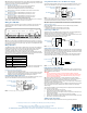
Setting Internal Jumpers E1 and E2 for Communication Mode
Internal jumpers are located on the circuit card inside the AXB-IRS4 enclosure. You will need
a Phillips-head screwdriver to open the enclosure..
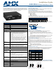
FIG. 1 AXB-IRS4
AXB-IRS4 Specifications
Control Controls up to four IR or serial devices
Memory 28K bytes (total); stores up to 200 control commands in each port.
Power requirement 12 VDC
Power consumption 125 mA
Supported baud rates 300, 600, 1,200, 2,400, 4,800, 9,600, 19,200
Front Panel Components
AxLink LED The AxLink LED blinks when there is AxLink or RS-232
communication activity or a memory error. If an AMX system
controls the AXB-IRS4, the green AxLink LED indicates the
following power and data activity, or memory errors:
• One blink per second: Power is active and the AxLink is
functional.
• Full on: Power is active and AxLink communication is not
functional.
• Fast blink: There is a memory error. A memory error can be
caused by a power-deficient battery. Follow the instructions
under Replacing the Lithium Battery section. If the error
continues, contact AMX technical support for assistance.
• If a PC system controls the AXB-IRS4, the green AxLink LED
blinks when RS-232 data is received or transmitted.
DEVICE
DIP switch
8-position DIP switch that sets the AXB-IRS4's device number so
that the Central Controller sends the proper control commands to
the correct device. See Setting the Device DIP Switch for details.
CARRIER/BAUD
DIP switch
8-position DIP switch that sets the carrier/No Carrier (NC) option
on the AXB-IRS4 ports, and the data transmission speed.
See Setting the Carrier/BAUD DIP switch for details.
IR/Serial LEDs
(1-4)
The red IR/SERIAL LEDs blink when the AXB-IRS4 transmits IR
or serial data on ports 1 through 4.
Rear Panel Components
4 IR/Serial
connectors
2-pin captive wire connector for each IR/serial port.
AxLink/RS232
connector
4-pin captive wire connector that supports AxLink or RS-232 data
communications.
• If you have an AMX system, use an AxLink cable to connect to
the control system.
• If you have a PC, use a DB-9 or DB-25 RS-232 cable to connect
to the PC. See Wiring the AXB-IRS4 for details.
PWR connector 2-pin captive wire connector connects an external 12 VDC power
supply to the AXB-IRS4. An external power supply should be used
when the distance between the AXB-IRS4 and control system
exceeds the wiring guidelines described under Wiring Guidelines.
Battery Lithium battery backup for stored control commands
Enclosure type Metal with black textured finish
Weight 1.12 lbs (508 grams)
Dimensions 1.51" x 5.55" x 5.45" (38.4mm x 141.0mm x 138.4mm)
Mounting options • Flat surface
• Rack mount, with optional AC-RK Rack Kit
DEVICE DIP Switch Settings
Position
12345678
Value
1 2 4 8 16 32 64 128
FIG. 2 CARRIER/BAUD DIP switch
RS-232 Baud Rate Settings
Baud
Rates
DIP Switches
678
300 Off Off Off
600 On Off Off
1,200 Off On Off
2,400 On On Off
4,800 Off Off On
9,600 On Off On
19,200 Off On On
FIG. 3 Internal jumpers E1 and E2: Communication Settings
1 2 3 4 5 6 7 8
NC
Baud rate settings
RS232/PCTouch mode select
Carrier signal enable/disable
AXM
AXP
RX
TX
AxLink
AXM
AXP
RX
TX
RS232