
User Guide


Camera Balancing Guide
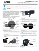
AXB-PT10/15 PosiTrack Camera Controllers
PT10/15 Camera/Lens Balancing
The camera/lens assembly should be mounted so the tilt axis is capable of
going through the optical axis of the camera, assuming the optical center-
line is between 1/2" (12.70 mm) and 5" (127.00 mm) above the mounting
plane of the camera lens. The mounting platform (camera cradle) allows the
camera/lens to be mounted with its center of gravity on the tilt axis. The
maximum weight of the camera/lens assemblies on the PT10 is 10 lbs.
(4.54 kg) and on the PT15 is 15 lbs. (6.80 kg). The camera cradle is
mounted to the Tilt Hub (FIG. 1).
To find the center of gravity of the camera/lens/cradle assembly use a pipe
or dowel-rod to balance the assembly, as shown in FIG. 3.
Caution: Do not lift the PT10/15 by the Camera/Lens cradle as this could
damage internal components.
To mount and balance the camera/lens:
1. Separate the camera mount and the cradle support bracket by remov-
ing the two 1/2" screws on the underside of the assembly (see FIG. 2)
using a 3/32" Allen wrench.
2. Install the camera alignment peg to the mount at the position that best
fits the camera/lens.
3. Secure the camera/lens to the mount (at the camera alignment peg)
with the 1/2" screw and 1/10" thick washer supplied
(see FIG. 2).
4. Place the assembly on a balancing beam and while maintaining the
cradle centered on the pipe, slide the camera along the cradle’s
grooves until the camera and cradle remain balanced on the beam
(FIG. 3). Verify balance with a spirit level.
5. Mount the camera as close to the Tilt Hub as possible to obtain a true
center of gravity.
6. Re-attach the camera mount (with camera/lens) to the cradle support
bracket using the two 1/2" screws.
7. Take the entire camera/mount and cradle assembly and align the lens
with the Tilt Hub so that the vertical-axis intersects the center of the
camera’s iris, as shown in FIG. 4.
8. Mark the position of the cradle support bracket on the Tilt Hub (for
later attachment).
9. Remove the camera/lens and mount piece from the support bracket by
unscrewing the two 1/2" screws on the underside of the camera
mount.
10. Secure the support bracket to the Tilt Hub (at the same position
marked for the iris alignment) on the PT10/15 with some or all of the
four 1/2" screws and washers.
11. Secure the camera/mount to the support bracket by using the two 1/2"
screws.
12. Support the weight of the camera cables with a wire tie attached to the
wire tie mount on the lower corner of the face of the PT10/15 (FIG. 5).
Note: The camera/lens cradle can be mounted on either side of the cradle
support bracket.
IMPORTANT! READ THIS DOCUMENT BEFORE MOUNTING CAMERA
Proper balance of the camera mount (with camera/lens/cradle) will result in optimal performance. Follow
these balancing instructions prior to operation. Failure to balance the camera mount can result in poor
performance.
FIG. 1 Tilt Hub dimensions for the PT10/15
FIG. 2 Camera bracket assembly
0.750"
19.05 mm
0.750"
19.05 mm
0.00"
0.00"
Position
markers
Camera
points in this
direction
0.56"
39.62 mm
0.750
"
19.05 mm
0.250"
6.35 mm
0.250"
6.35 mm
0.750"
19.05 mm
Mounting holes (three sets)
Cradle
support
bracket
Camera alignment peg
Camera mount
(
underside view)
Camera\Lens
cradle assembly
(side view)
FIG. 3 Balancing the camera/lens cradle assembly
FIG. 4 Iris alignment with vertical tilt-axis
FIG. 5 Pedestal mount
cradle
(bottom view)
balancing beam
Marker
points
Iris
Ver tical
tilt-axis
Cradle support
bracket
Wire
tie-
mount
Camera mount
assembly
Pedestal mount