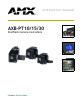
instruction manual AXB-PT10/15/30 PosiTrack Camera Controllers C a m e ra C o n t r o l l e r s
AMX Limited Warranty and Disclaimer AMX Corporation warrants its products to be free of defects in material and workmanship under normal use for three (3) years from the date of purchase from AMX Corporation, with the following exceptions: • Electroluminescent and LCD Control Panels are warranted for three (3) years, except for the display and touch overlay components that are warranted for a period of one (1) year.
Table of Contents Table of Contents Introduction ...............................................................................................................1 Specifications .................................................................................................................... 2 Lens Control Modes .......................................................................................................... 3 Servomotor Mode........................................................................
Table of Contents Programming .......................................................................................................... 27 Configuration Commands ............................................................................................... 27 Channel Commands ....................................................................................................... 35 Pan/tilt functions...........................................................................................................
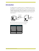
Introduction Introduction The AXB-PT10 PosiTrack 10, AXB-PT15 PosiTrack 15, and AXB-PT30 PosiTrack 30 Camera Controllers (FIG. 1) are camera/lens controllers used for precise camera-positioning applications. Each PosiTrack unit supports both AXlink and RS-232 control protocols and connects directly to an AXlink network. All controllers contain on-board intelligence for consistent motion and lens control.
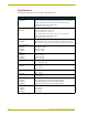
Introduction Specifications The following table lists the specifications for all PosiTrack units. Specifications Dimensions (HWD): AXB-PT10 Camera controller: 5.85" x 5.20" x 4.92" (14.86 cm x 13.22 cm x 14.70 cm) Camera mount: 0.65" x 2.26" x 3.23" (1.75 cm x 5.74 cm x 8.21 cm) Cradle support bracket: 3.64" x 5.50" x 0.20" (9.25 cm x 13.97 cm x 0.51 cm) Dimensions (HWD): AXB-PT15 Camera controller: 6.43" x 5.61" x 5.38" (16.32 cm x 14.25 cm x 13.67 cm) Camera mount: 0.65" x 2.26" x 3.23" (1.75 cm x 5.
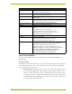
Introduction Specifications (Cont.) DIP Switches: • (S2) - RS-232 communication (baud rate) • (S5) - AXlink communication (device #) Presets: Stores up to 255 presets for pan, tilt, zoom, focus, and iris operations; 127 of those presets return a status when queried.
Introduction Speed mode moves the lens when the voltage deviates from the center point of its range. The farther the voltage moves away from the center point of reference, the faster the lens motor moves. The lens must have POT outputs when recalling a preset in this mode,. The outputs pass to the PosiTrack unit, and when the received voltage level matches the level stored in the preset, the voltage returns to zero. Servomotor speed mode lenses not having POT outputs do not have preset recall capability.
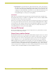
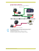
Introduction Sample Product Application FIG. 2 shows a sample camera control application using the AXB-PT10. Application #1 - AXlink AMX AXP-PLV AMX AXB-PT10 AMX Local Power Supply PWR cable RS-232 / 422 AXP GND AXM AXlink PWR GND 485EN TX1 RX1 RX RX TX TX V CTS2 GND RTS2 RS-232 RX2 AXlink TX2 AMX AXB-EM232 (rear view) 12VDC PWR AXlink AMX ABS (AXlink Bus Strip) AMX PS2.
Introduction 6 AXB-PT10/15/30 PosiTrack Camera Controllers
Pre-Installation Pre-Installation There are four SPDT slide switches in the lens control section (FIG. 3). Three of the switches toggle the lens control selection between servomotor or motor mode hardware for control of zoom, focus, and iris. The fourth selects between ± 6 VDC and ± 12 VDC control for motor mode lens functions. An SPDT switch is a Single Pole-Double Throw switch. This switch is completed at both positions. An example is the Volt switch that is active in both the 6 and 12 positions.
Pre-Installation AXlink LED S6 VOLT 6 12 S M S M S M RS-232 S1 ZOOM S3 FOCUS S4 IRIS AXlink FIG. 3 Lens control section (back panel) Setting zoom, focus, and iris switches to servomotor or motor mode Both PosiTrack units support servomotor (+2.5 to +7.5 VDC operating range) and direct-drive motor (± 6 VDC or ± 12 VDC operating range) lens control. The table below shows how to set the switches for servomotor mode (S) or motor mode (M).
Pre-Installation The RS-232 factory default communications settings are: 9600 baud, No Parity, 8 bits, and 1 stop bit. The following table lists the RS-232 Port DB-9 (male) pinouts. RS-232 Port DB-9 (male) Pinouts Pin Signal Function 1 N/A N/A 2 RXD RXD 3 TXD TXD 4 N/A N/A 5 GND GND 6 N/A N/A 7 RTS RTS 8 CTS CTS 9 N/A N/A The following table lists the RS-232 DIP switch settings.
Pre-Installation The AXlink device number range is 1-255. The Device DIP switch positions determines their values, based on the following table: Device DIP Switch (S5) Settings and Values Position 1 2 3 4 5 6 7 8 Value 1 2 4 8 16 32 64 128 After setting the AXlink device number, remove and reconnect the AXlink connector on the PosiTrack unit to save the new number.
Pre-Installation Pins that connect the control panel to the motherboard FIG. 7 Control panel removal for PT10 and PT15 6. Carefully pull the cover straight up from the main unit, until the bottom edge of the cover clears the connector panel and then slide it backwards (as seen in FIG. 8). FIG. 8 Removing cover on the PT10 and PT15 Accessing the AXB-PT30 Internal Jumpers Jumpers J6 - J8, located on the circuit board inside the AXB-PT30, set the communication mode to AXlink (factory default) or RS-232.
Pre-Installation BHSC screws (two screws on top) Connector panel (four screws) BHSC screws (six screws on each side) PosiTrack 30 BHSC screws (two on the rear) RS-232 LENS LENS POWER AMX CAM AXlink FIG. 9 Pan-head screw locations Setting the Internal Jumper Communication Mode 1. Locate jumpers J6, J7, and J8 communication mode jumpers on the Mother PCB (FIG. 10). The connectors and the main board are mounted onto the pan base. 2. Set the jumpers for either AXlink or RS-232 communication.
Pre-Installation For RS232 stand-alone mode, the 8-position AXlink Device DIP switch must be set to all off (down position). 4. Carefully place the cover back onto the main unit by sliding it over the internal gears and motherboard. 5. Align the Control panel screw holes. Make sure the cables are not pinched in the back panel or drive gears. 6. Insert the 14 BHSC screws and tighten securely using the 1/16" Allen wrench.
Pre-Installation 14 AXB-PT10/15/30 PosiTrack Camera Controllers
Installation Installation IMPORTANT! READ THIS DOCUMENT BEFORE MOUNTING CAMERA. Proper balance of the camera mount (with camera/lens/cradle) will result in optimal performance. Follow these balancing instructions prior to operation. Failure to balance the camera mount can result in poor performance. The PosiTrack units enable pan and tilt functionality for mounted camera/lens assemblies and provides lens control functions for teleconferencing lenses.
Installation Position marker (on the outer surface) Camera points this way when the pan drive is in the center of its range of motion (Home position) Ø 3.453" 87.7 mm 3.00 BHC" 76.20 mm 3.45" (87.7mm) FIG. 12 Tilt Hub (Mounting plate) dimensions Each PosiTrack unit can be mounted to camera mounts such as the TM-CAM, WM-CAM, and PM-CAM as shown in FIG. 13. Cradle support bracket Camera mount assembly PM-CAM (Pedestal mount) Wire tie-mount FIG.
Installation 0.750" 19.05 mm 0.750" 0.00" 19.05 mm Position markers 0.750" 19.05 mm 0.250" 6.35 mm Camera points in this direction 0.00" 0.250" 6.35 mm 0.750" 19.05 mm 0.56" 39.62 mm FIG. 14 Tilt Hub dimensions for the PT10/15 units Do not lift the PosiTrack unit by the Camera/Lens cradle as this procedure could damage internal components. To mount and balance the camera/lens: 1.
Installation cradle (bottom view) balancing beam FIG. 16 Balancing the camera/lens cradle assembly 6. Re-attach the camera mount (with camera/lens) to the cradle support bracket using the two 1/2" screws. 7. Take the entire camera/mount and cradle assembly and align the lens with the Tilt Hub so that the vertical-axis intersects the center of the camera’s iris, as shown in FIG. 17. Marker points Iris Vertical tilt-axis FIG. 17 Iris alignment with vertical tilt-axis 8.
Installation IMPORTANT! READ THIS DOCUMENT BEFORE MOUNTING CAMERA. Proper balance of the camera mount (with camera/lens/cradle) will result in optimal performance. Follow these balancing instructions prior to operation. Failure to balance the camera mount can result in poor performance. PT30 Camera/Lens Mounting and Balancing The camera/lens assembly should be mounted so the tilt axis is capable of going through the optical axis of the camera, assuming the optical centerline is between 1/2" (12.
Installation Camera/lens cradle assembly FIG. 19 Camera/lens cradle assembly mounting Tilt-axis mount slots FIG. 20 Balancing the camera/lens cradle assembly 7. Secure both the camera mounting and tilt-axis screws. 8. Take the entire camera/lens assembly and slide it along the Tilt Hub until the vertical-axis of the PT30 intersects the center of the camera’s iris. Refer to the PT10 and PT15 Camera/Lens Mounting and Balancing section on page 16 for more information on alignment. 9.
Installation FIG. 21 shows the location of each connector on the AXB-PT10/15. AXB-PT10 (side view) Camera control RS-232 DB-9 (male) connector Control panel Lens control DB-15 high density (female) connector Lens Power switch Pin 1 power switch for DB-15 connector LENS POWER AMX AXlink 4-pin (male) connector CAM Wire tie-mount FIG. 21 Control panel location on the AXB-PT10/15 The PosiTrack Controller receives all power from the +12 VDC and GND connections on the fourpin AXlink connector.
Installation Preparing captive wires You will need a wire stripper and flat-blade screwdriver (approximately 1/8") to prepare and connect the captive wires. Never pre-tin wires for compression-type connections. 1. Strip 0.25 inch (6.35 mm) of insulation off all wires. 2. Insert each wire into the appropriate opening on the connector, according to the wiring diagrams and connector types described in this section. 3. Turn the screws clockwise to secure the wire in the connector.
Installation Using the AXlink connector with an external RS-232 control device or PC (StandAlone only) To use the AXlink 4-pin connector with a PC or other RS-232 controller, wire the AXlink connector to a DB-9 female connector, as shown in FIG. 23. Connector pins 2, 3, and 5 are used for data and ground. For some applications requiring hardware handshaking, it may be necessary to strap pins 7 (request to send) and 8 (clear to send) together.
Installation Using the lens control DB-15 HD (high density) connector The PosiTrack Controllers are designed to control servomotor and motor mode camera lenses. See the Pre-Installation section on page 7 to set the lens switches for servomotor or motor mode. FIG. 24 shows the DB-15 HD connector pin numbers. Pin 5 Pin 1 Pin 6 Pin 10 Lens control DB-15 HD (female) connector wiring pinouts Pin 15 Pin 11 FIG.
Installation Lens Control DB-15 HD Connector Pinouts for Servomotor Mode (Cont.) PosiTrack DB-15 HD connector functions Pin Direction Lens function 6 Zoom-speed/position Output Zoom-positional/speed mode 7 Focus-speed/position Output Focus-positional/speed mode 8 Iris-local/auto Output Iris-local/auto select 9 Iris-speed/position Output Iris-positional/speed mode 10 VREF-A (+7.5V) Input VREF-A (+7.5 V). The reference voltage must be present to operate correctly in servomotor mode.
Installation Tilt Characteristics The tilt drive is factory set to a maximum tilt range of ± 90° (for a total of 180°). Tilt limit stops refer to the vertical range of motion available to the PosiTrack unit and are set via the Axcess program. The center position marks the center of the range. Setting the adjustable tilt-limit stops The Central Controller should be programmed before beginning. Refer to the Specifications section on page 2 for more information on programming devices.
Programming Programming The AXB-PT10, AXB-PT15, and AXB-PT30 control capabilities for camera functions include: • Pan • Focus (servomotor; speed) • Tilt • Focus (motor drive) • Zoom (servomotor; positional) • Iris (servomotor; positional) • Zoom (servomotor; speed) • Iris (servomotor; speed) • Zoom (motor drive) • Iris (motor drive) • Focus (servomotor; positional) The PosiTrack Controllers are controlled with device-specific channel settings and Axcess Send_Commands.
Programming Variables for the Configuration Commands (Cont.) Parameters Description Speed 0 to 127; where 0 is the slowest and 127 is the fastest (default). Deviation 0 to 127; where 0 is most accurate but can have some jitter. Default is 2, meaning the position can be within + 2 from the specified position. Distance 0 to 127; distance from the specified position. Ramp Time 1 to 255; time in 10ms increments it takes the motor drives to ramp up to speed.
Programming Configuration Commands (Cont.) CLEAR HOME Clears the current home position and goes to the default setting and clears presets. CLEAR LIMIT ALL Clears all of the limits. CLEAR LIMIT DOWN Clears the tilt-down limit. CLEAR LIMIT LEFT Clears the pan-left limit. CLEAR LIMIT RIGHT Clears the pan-right limit. CLEAR LIMIT UP Clears the tilt-up limit . CURRENT SPEED PRIORITY=CHANNEL Changes the operational mode of channels 31, 32, 35, and 36.
Programming Configuration Commands (Cont.) FOCUS PRESET=SPEED This is applicable only if the FOCUS SIGNAL=S command is in effect, and the FOCUS switch is set to the S position (servomotor mode). Sets the FOCUS voltage output to recall speed presets. Syntax: SEND_COMMAND CAM,"’FOCUS PRESET=SPEED’" The command for FOCUS output to servomotor mode or motor mode MUST be configured to match the switch settings.
Programming Configuration Commands (Cont.) GET VERSION (version 3.00 or higher) Displays the current firmware version (Boot and Download) on the terminal. The Boot version sent back is determined by checking the version in flash memory. Syntax: SEND_COMMAND CAM,"’GET VERSION’" This command is issued from Terminal Emulator mode. When using a NetLinx master, the ’MSG ON’ command must first be issued to see the status.
Programming Configuration Commands (Cont.) IRIS SIGNAL=S This setting corresponds to the S position (servomotor mode) setting on the IRIS switch. Sets the Iris output to be a servomotor output. Syntax: SEND_COMMAND CAM,"’IRIS SIGNAL=S’" The command for IRIS output to servomotor mode or motor mode MUST be configured to match the switch settings. IS Sets the lens’ Iris mode to speed. Syntax: SEND_COMMAND CAM,"’IS’" This command can be used only for servomotor mode.
Programming Configuration Commands (Cont.) READ ALL Forces the device to read and update levels to the Central Controller. Syntax: SEND_COMMAND CAM,"’READ ALL’" RUN TESTS Runs and checks error values 244 and 245 to see if the gears are properly aligned to their respective grooves. Syntax: SEND_COMMAND CAM,"’RUN TESTS’" Refer to the Diagnostic error values section on page 41 for more detailed information.
Programming Configuration Commands (Cont.) ZAP! Syntax: Initializes all memory in SEND_COMMAND CAM,"’ZAP!’" the unit. This includes speed settings, deviation settings, configuration settings, and all presets. Warning! This command clears all user-defined settings. ZOOM PRESET=POS Sets the Zoom voltage output to recall positional presets (default).
Programming Channel Commands Use channel commands to program pan/tilt, servomotor positional, servomotor speed, and motor mode functions.
Programming Motor mode lens functions Motor Mode Lens Functions Channel State Function 1 On Iris (+) at current speed 3 On Zoom (+) at current speed (increases output voltage) 4 On Focus (+) at current speed 5 On Iris (-) at current speed 7 On Zoom (-) at current speed (decreases output voltage) 8 On Focus (-) at current speed 10 On Iris (+) at maximum speed 12 On Zoom (+) at maximum speed (output minimum voltage) 13 On Focus (+) at maximum speed 14 On Iris (-) at maximum sp
Programming Status Channels Channel State Function 29 On Unit is panning 30 On Unit is tilting 95 On Unit has found its max pan left limit 96 On Unit has found its max pan right limit 97 On Unit has found its max tilt up limit 98 On Unit has found its max tilt down limit 228 On Unit has found its HOME position 248 On Unit is finding HOME position The following is an example of how to use the above functions to obtain a visual status of the movement of the PosiTrack without being
Programming Levels The following table lists the Axcess/NetLinx levels.
Programming Parameters - Send_Commands (Cont.) Parameters Description Time (optional) If specified, 0 to 255 in tenths of a seconds; if not specified, at current rate. Position 0 to 255; value of POT input. Corresponds to a position of the unit. 0 is one end of the POT and 255 is the other end. Not directly related to an output level voltage. 0 to 65535 when using the 'AD MODE x 10' command, or for pan/ tilt commands. Corresponds to a position of the unit.
Programming Positional Commands (Cont.) GL This command can be used for all modes. Turns on the specified output at the current speed until the specified position (as read by the Pan or Tilt encoder) is reached. Syntax: "’G
Programming Positional Commands (Cont.) PR This command can be used for servomotor positional mode applications. Syntax: Sets the ramp rate of the specified output "’P
Programming Error Values and Descriptions Error Description 230 Shows there is an error on the system. This value always appears in conjunction with another number. It acts as a precursor to any other error messages, as an announcement that an error has been found and the following values are the errors found. 240 Shows that there is a problem with the Pan Encoder on the PosiTrack. The encoder is a device that counts the revolutions of the pan motor.
Programming The following table lists preset commands. Preset Commands CANCEL PRESET Immediately stops any active preset recall in motion. CP Clears a preset from memory. Examples: SEND_COMMAND CAM, "’CANCEL PRESET’" Syntax: "’CP’" Variables: preset = 1 - 255 Examples: SEND_COMMAND CAM, "’CP1’" Clears Preset 1. SEND_COMMAND CAM, "’CP100’" Clears Preset 100. RP Recalls a stored preset.
Programming Preset Commands (Cont.) SEND_COMMAND CAM,"’RP10S64’" Recalls preset 10. If any are in positional mode, the current voltages for zoom, focus, and/or iris will be ramped to the preset voltages at the current speed. If any are in speed mode, the motor drive outputs for zoom and/or focus will move at half speed (64). Pan/tilt outputs will move at half speed. Turns on channel 110 when preset 10 is reached. SEND_COMMAND CAM,"’RP10T100S64’" Recalls preset 10.
Programming RS-232 Commands (Cont.) CTSPSH Enables pushes, releases, and status information on channel 255 for CTS hardware handshake input. HSOFF Disables hardware handshaking (default). Syntax: "’CTSPSH’" If CTS is high, channel 255 is On. Example: SEND_COMMAND CAM,"’CTSPSH’" Syntax: "’HSOFF’" Example: SEND_COMMAND CAM,"’HSOFF’" HSON Syntax: Enables hardware handshaking.
Programming RS-232 Send_Strings PosiTracks have special Send_String escape sequences. If any of the three-character combinations listed below are found anywhere within a Send_String program instruction, they are treated as a command and not the literal characters. RS-232 Send_Strings "'27,18,0'" Clears the ninth data bit to 0 for all subsequent characters to be transmitted. It is used in conjunction with the 'B9MON' command.
Programming General Format (Cont.) Byte No. Type Range Direction 4 Pan Feedback 0-65535 From PT 5 Tilt Feedback 0-65535 From PT 6 Zoom Pot Feedback 0-65535 From PT 7 Focus Pot Feedback 0-65535 From PT RS-232 Levels that are valid are 0-7. The following table lists the request functions sent to PosiTrack units.
Programming Response mask Data is automatically sent if the PosiTrack units receive a change request. The response mask should be disabled if the change request data is not used. Bits in the response mask (the Return/Respond Strings from the PosiTrack Units table) turn data off.
Upgrading the Firmware Upgrading the Firmware Upgrading the Firmware Using NetLinx Studio The NetLinx Studio application can perform firmware upgrades for both Axcess and NetLinx devices using the options in the NetLinx Studio Firmware sub-menu. Upgrading Firmware on Axcess Systems 1. Choose Tools > Firmware > Download to Axcess Device to open the Axcess Firmware Download dialog. The default Baud Rate for Axcess is 38400 baud and for NetLinx is 38400 baud. 2. Adjust the Comm Settings, if necessary: a.
Upgrading the Firmware Click OK to confirm the Comm Settings and Target Device information, and download the selected .TSK file to the specified device using the selected communications port. 8. The File Transfer dialog shows the progress of the download. Click Cancel to cancel the download. Canceling the firmware download in mid-progress can damage the on-board firmware. 9. Once the .
Upgrading the Firmware 4. Using the up/down arrow keys, select the device to be programmed. 5. Press ENTER for each device as it is selected 6. Press F4 to program the selected device; a loading message appears. 7. Once the .TSK file has been downloaded, the device AXlink LED will begin to flash repeatedly for about 6 seconds while the on-board firmware is stored and updated. After wards, the AXlink LED blinks once (to indicate proper communication) and the unit runs a self-calibration routine. 8.
048-004-2370 1/05 ©2005 AMX Corporation. All rights reserved. AMX, the AMX logo, the building icon, the home icon, and the light bulb icon are all trademarks of AMX Corporation. AMX reserves the right to alter specifications without notice at any time. *In Canada doing business as Panja Inc. AMX reserves the right to alter specifications without notice at any time.