
User Guide


Pre-Installation
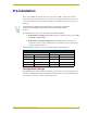
10
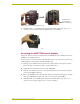
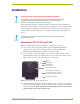
AXB-PT10/15/30 PosiTrack Camera Controllers
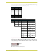
The AXlink device number range is 1-255. The Device DIP switch positions determines their
values, based on the following table:
After setting the AXlink device number, remove and reconnect the AXlink connector on the
PosiTrack unit to save the new number.
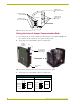
Accessing the AXB-PT10 and AXB-PT15 Internal Jumpers
Jumpers J6 through J8, located on the circuit board inside the PT10 and PT15, set the
communication mode to AXlink (factory default) or RS-232.
You need a 5/64" (1.98 mm) and 1/16" (1.59 mm) Allen wrench to open the unit, and a pair of non-
conducting pliers to set the jumpers using the following steps.
1. Discharge any accumulated static electricity from your body before removing the enclosure.
Remove the static electricity by touching a grounded metal object.
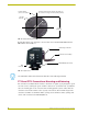
2. Unplug all connectors from the rear panel of the PosiTrack unit.
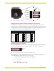
3. Remove the four screws, located around the connector panel (FIG. 6), by using the 1/16" Allen
wrench. BHSC is the abbreviation for the Button Head Socket Cap screws.
4. Carefully pull the connector panel away from the main unit until the bottom edge of the cover
clears the connector panel. Be careful not to damage the pins attached to the connector panel.
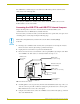
FIG. 7 illustrates how to remove the control panel.
5. Using the 1/16" Allen wrench, remove the 14 BHSC screws, from the left, right, top, and back
sides of the PosiTrack unit.
Device DIP Switch (S5) Settings and Values
Position 12 34567 8
Value 1 2 4 8 16 32 64 128
Remove the control panel before you remove the cover, in order to avoid any damage
to the unit.
FIG. 6 Pan-head screw locations
AMX
LENS POWER
CAM
RS-232
LENS
AXlink
BHSC screws
(two screws
in rear)
BHSC screws
(five screws on each side)
BHSC screws
(two screws on top)
Tilt-head screws (four
screws available)
Connector panel
(four screws)