
User Guide

Installation
20
AXB-PT10/15/30 PosiTrack Camera Controllers
7. Secure both the camera mounting and tilt-axis screws.
8. Take the entire camera/lens assembly and slide it along the Tilt Hub until the vertical-axis of
the PT30 intersects the center of the camera’s iris. Refer to the PT10 and PT15 Camera/Lens
Mounting and Balancing section on page 16 for more information on alignment.
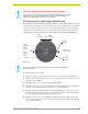
9. Mark the position of the white tilt-axis marker on the camera/lens cradle (use this position for
later attachment of the camera/lens assembly to the Tilt Hub).
10. Remove the camera/lens from the cradle.
11. Secure the camera/lens assembly to the Tilt Hub by using the lens centerline markings for the
camera as a reference (see previous step) with the eight 32x 3/4" screws and washers removed
in step 1.
12. Re-attach the camera to its previous position on the cradle.
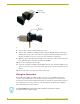
Wiring the Connectors
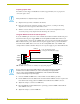
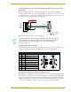
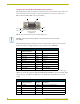
Each PosiTrack Controller has an RS-232 DB-9 connector, lens control DB-15 high-density
connector, and an AXlink 4-pin connector. Always provide enough cable to accommodate the
desired range of motion for the PosiTrack units and their camera/lenses. The Lens Power switch on
the control panel, removes any power noise on the incoming video by turning power On/Off to
Pin 1 of the DB-15 lens control connector.
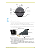
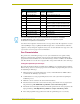
FIG. 19 Camera/lens cradle assembly mounting
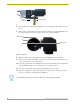
FIG. 20 Balancing the camera/lens cradle assembly
Camera/lens
cradle assembly
Tilt-axis
mount slots
The LENS POWER switch can turn power Off to the DB-15 pin 1 when the camera/
lens is powered from a separate supply.