Operation/Reference Guide AXB-TC and AXB-TCR Television Controllers (& Receivers) Axcess Controllers Last Revised: 7/10/2007
AMX Limited Warranty and Disclaimer All products returned to AMX require a Return Material Authorization (RMA) number. The RMA number is obtained from the AMX RMA Department. The RMA number must be clearly marked on the outside of each box. The RMA is valid for a 30-day period. After the 30-day period the RMA will be cancelled. Any shipments received not consistent with the RMA, or after the RMA is cancelled, will be refused. AMX is not responsible for products returned without a valid RMA number.
Table of Contents Table of Contents AXB-TC and AXB-TCR Television Controllers .....................................................1 Overview .................................................................................................................. 1 Specifications............................................................................................................ 2 Applications ..............................................................................................................
Table of Contents ii AXB-TC and AXB-TCR Television Controllers (& Receivers)
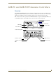
AXB-TC and AXB-TCR Television Controllers AXB-TC and AXB-TCR Television Controllers Overview The AXB-TC and AXB-TCR Television Controllers are intelligent, microprocessor-controlled systems equipped with a lithium battery to protect stored memory. The television controllers can control a variety of Infrared-controlled devices such as televisions, audio receivers, and videocassette recorders. FIG. 1 shows the front and rear panels of the AXB-TCR.
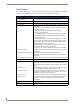
AXB-TC and AXB-TCR Television Controllers Specifications The following table list the product specifications for the television controllers. Other than the IR Input Window (on the AXB-TCR only), the specifications for the TC and TCR are identical. AXB-TC/TCR Specifications Dimensions (HWD): (with connectors) Power consumption: • 1.29" x 3.33" x 5.54" (32.8 mm x 84.6 mm x 140.
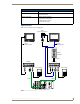
AXB-TC and AXB-TCR Television Controllers AXB-TC/TCR Specifications (Cont.) Mounting options: Flat surface Included accessories: • CC-IR TV Sensor (CC-XPS sensor) • CC-IRC IR Emitter Optional accessories: • SE-TC Security Enclosure • PCS Power Current Sensor • VSS2 Video Sync Sensor • 12 VDC Power supply Applications FIG. 2 shows a sample system configuration.
AXB-TC and AXB-TCR Television Controllers 4 AXB-TC and AXB-TCR Television Controllers (& Receivers)
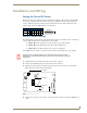
Installation and Wiring Installation and Wiring Setting the Device DIP Switch The eight-position Device DIP switch sets the identification number for the television controller. Make sure the device number matches the number assigned in the AXCESS software program. The quick reference table below shows the switch positions and their numeric value. In the example below, the numeric value of the Device DIP switch is 97 (1+32+64=97).
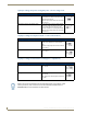
Installation and Wiring JI jumper settings: TV power sensing/TV power current sensing mode JI Jumper Settings: TV Power Sensing/TV Power Current Sensing Television Power Sensing mode To use this mode, connect a TVS TV Sensor to the television to detect horizontal scan frequencies up to 65 kHz. Place the 2-pin jumper on the JP1 connector pin's 1 and 2.
Installation and Wiring Wiring The TV sensor, IR emitter, AXlink, and 12 VDC power supply connectors are located on the rear panel of the television controller as shown in FIG. 1 on page 1. Do not connect power directly to the television controller. If you are using power from AXlink, disconnect the wiring from the Central Controller before connecting the wiring to the television controller.
Installation and Wiring IR Emitter connections Connect the CC-IRC IR Emitter to the IR Emitter connector, on the rear panel of the television controller (FIG. 3) to transmit IR control signals to the television. CC-IRC Television IR EMITTER connector GND SG FIG. 3 CC-IRC IR Emitter connector wiring diagram Axlink data and power connections Connect the Central Controllers's AXlink connector to the AXlink connector on the rear panel of the television controller for data and 12 VDC power, as shown in FIG.
Installation and Wiring Make sure to connect only the GND wire on the AXlink connector when using a 12 VDC power supply. Do not connect the PWR wire to the AXlink connector's PWR opening. PCS and Axlink data and power connections Connect the PCS Power Current Sensor to the TV Sensor connector, on the rear panel of the television controller (FIG. 6) to detect and control the television power status (on or off).
Installation and Wiring Installation Install the television controller on any flat surface or inside the optional SE-TC Security Enclosure, as described below: 1. Mount the Axcess Central Controller where it will be used. Then, connect the power supply. 2. Route the Axlink power and data cable, CC-IR TV Sensor cable, CC-IRC IR Emitter cable, and 12 VDC power supply from the television to the television controller's location. 3.
Installation and Wiring Television Power Sensor Adjustment After connecting the CC-IR to the television, the power sensing POT, on the rear of the television controller (see FIG. 1 on page 1), may require adjustment to detect the television's power status: Use a Phillips-head screwdriver and flat-blade tool (non-conducting) to adjust the POT screw. 1. Turn the television off. 2. Locate the POT screw on the circuit card and turn it clockwise 20 full turns or until it clicks.
Installation and Wiring 4. Turn the POT screw clockwise one-eighth turn to increase signal saturation. Then, send an IR control signal to the television. If the television performs correctly, go to step 5. If not, repeat this step until the television performs the correct operation. 5. Send an IR control signal to the television for all programmed operations. If an operation fails, go back to step 4. 6. Reattach the enclosure and refasten the two screws.
Installation and Wiring There is a danger of explosion if you replace the battery incorrectly. Replace the battery with the same or equivalent type, recommended by the manufacturer. Dispose of the used battery according to the manufacturer's instructions. Never recharge, disassemble, or heat the battery above 212 °F (100 °C). Never solder directly to the battery or expose the contents of the battery to water.
Installation and Wiring 14 AXB-TC and AXB-TCR Television Controllers (& Receivers)
Programming Information Programming Information Overview The television controllers are controlled with channel settings, IR functions, and Axcess Send_Commands. You create software programs with the AMX Axcess programming software. Use the programming information in this section with the Axcess Programming Guide to program television controllers. After you create the IRLIB program, download it to the non-volatile (battery protected) memory in the television controller.
Programming Information IR Functions (Standard Order) The following table lists the IR function, in their standard order.
Programming Information Send_Commands Use the Send_Commands listed in the following table to program the Axcess Central Controller and television controller. The device number range for the television controller is 1 through 255. Refer to the Axcess Programming Language instruction manual for additional programming information. Send_Commands CARON Enables an IR carrier signal after receiving a 'CARON' command. Example: SEND_COMMAND 1,'CARON' Enables the carrier signal for device 1.
Programming Information Send_Commands (Cont.) ?CTON Sends the current on-time pulse string "'CTON',
Programming Information Send_Commands (Cont.) 'PTOF',
Programming Information Send_Commands (Cont.) XCHM Changes the IR output pattern for the XCH command. Syntax: SEND_COMMAND ,'XCH-' Variable: Mode = 0-4 Example: SEND_COMMAND IR_1,'XCH 3' Sets the IR_1 device's extended channel command to mode 3. Mode 0 Example (default): [x] [x] SEND_COMMAND IR_1, 'XCH 3' Transmits the IR code as 3-enter. SEND_COMMAND IR_1, 'XCH 34' Transmits the IR code as 3-4-enter. SEND_COMMAND IR_1, 'XCH 343' Transmits the IR code as 3-4-3-enter.
Programming Information Firmware Upgrades Firmware upgrades allow you to install the latest available operating system for your AXB-TC or AXBTCR. The firmware reload is required anytime the unit's LEDs all flash at the same rate as the AXlink LED, or if all LEDs are full-on. To accomplish the upgrade, your computer must be connected to the Axcess Master Controller via a serial (RS-232) interface connecting to the AXlink DB-9 programming port input.
Programming Information 7. Upon completion of the upgrade, press F10 to exit SOFTROM. Firmware Device Number Version Number Type Number Loading status and device number FIG. 2 Loading status bar Firmware can be downloaded to multiple device numbers automatically. If multiple devices are selected, the bottom half of the loading bar will indicate the percentage complete for the selected devices.
Programming Information 9. Once the .TSK file has been downloaded, the program prompts you to reboot the Axcess Master. Click Yes to reboot, and the program initiates the reboot sequence. When the Master has rebooted, the Status LED on the front panel of the Master blinks once a second to indicate it is functioning properly. 10. Once it has rebooted, click OK.
AMX. All rights reserved. AMX and the AMX logo are registered trademarks of AMX. AMX reserves the right to alter specifications without notice at any time. ©2007 7/07 It’s Your World - Take Control™ 3000 RESEARCH DRIVE, RICHARDSON, TX 75082 USA • 800.222.0193 • 469.624.8000 • 469-624-7153 fax • 800.932.6993 technical support • www.amx.