“Perfecting Video with a No-Compromise Approach for Reproducing the Ultimate Film Experience” The Faroudja VP301 Video Processor With Picture Plus™ Technology Installation & Operation Instructions ª
TABLE OF CONTENTS History . . . . . . . . . . . . . . . . . . . . . . . . . . . . . . . . . . . . . . . . . . . . . . . . . . . . 2 Licensees and Awards . . . . . . . . . . . . . . . . . . . . . . . . . . . . . . . . . . . . . . . . 3 System Description . . . . . . . . . . . . . . . . . . . . . . . . . . . . . . . . . . . . . . . . . . 4 Inventory List . . . . . . . . . . . . . . . . . . . . . . . . . . . . . . . . . . . . . . . . . . . . . . . 5 Caution Notes . . . . . . . . . . . . . . . . . . . . . . .
HISTORY Some Video History and the Faroudja Approach Faroudja Laboratories, located in northern CaliforniaÕs Silicon Valley, was founded in 1971 by Yves and Isabell Faroudja to develop state-of-the-art video processing technology. Over the last 26 years, Faroudja Laboratories has developed hundreds of advanced electronic processes to improve video enhancement, noise reduction and NTSC encoding/ decoding technologies.
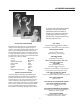
LICENSEES AND AWARDS On June 24, 1998 Yves Faroudja was awarded the prestigious Charles F. Jenkins Lifetime Achievement Award from the Academy of Television Arts & Sciences for his video processing technology. Faroudja’s first Emmy was awarded in 1991. Some of this award winning technology is used in the VS50.
SYSTEM DESCRIPTION 75-Ohm terminator switch is provided and should be in the ON position if the input loop is not used. The S-Video input uses a standard 4-pin connector. This input is not available for a looped operation and is terminated internally. The RGB and Component inputs use BNC connectors. As with the video input, these inputs can be looped to other devices. Selectable 75-Ohm terminations are provided.
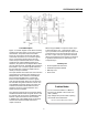
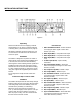
SYSTEM DESCRIPTION Circuit Description When using the RGB or Component inputs, Sync is derived from the G or Y input signals unless sync is provided to the Composite Sync input. The Composite Sync input will override the sync from the G or Y inputs. The sync signal then feeds the VP301 clock generator and is used as a reference to generate Horizontal Sync, Vertical Sync and Composite Sync. Figure 1 is a block diagram of the VP301 showing signal flow and the location of front panel controls and switches.
TECHNICAL HIGHLIGHTS Picture Plus™ Technology Ð The VP301 is called a Line Multiplier. However, just increasing the number of lines can make the image worse. This is where Picture Plusª technology becomes critical. Picture Plus represents a complex, multi-stage process that takes advantage of all the patented Faroudja circuitry for color, motion and detail processing. How these circuits improve the picture are outlined below.
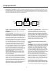
Y/ C RGB SYNC B-Y Y R-Y LASERDISC PLAYER VIDEO SWITCHER VIDEO TUNER R COMPOSITE VIDEO G VP301 VIDEO PROCESSOR B SYNC MONITOR VIDEO PROJECTOR OR MONITOR WITH 7''or 8'' CRT TUBES COMPUTER DISPLAY VCR TYPICAL VP301 UTILIZATION TYPICAL VP301SYSTEM SYSTEM UTILIZATION circuitry, while vertical resolution is a function of the scanning frequency (the number of scan lines in each picture).
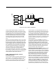
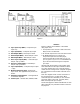
INSTALLATION INSTRUCTIONS Figure 2 Unpacking Rear Panel I/O Remove the VP301 from the shipping container and examine it for any signs of shipping damage or missing items, (check inventory list on page 5). 11. Video Termination Switch Ð Select ON when not looping the Video signal to other video devices, (75 Ohm). All shipping materials should be saved if the unit is to be moved or should need to be returned for service or repair. 12. Video Input (BNC) Ð Composite Video Input 13.
Figure 3 Interface Figure 3 outlines the installation of the VP301 using inputs from: 16. Sync Input Loop (BNC) Ð Composite Sync Input Loop 17. Sync Input (BNC) Ð Composite Sync Input 1. A composite source such as a DVD Laser Disk Player, VCR or TV Receiver. 18. Red Output (BNC) Ð Red Output 714mV 2. An S-Video input such as a S-VHS VCR or DVD 19. Green Output (BNC) Ð Green Output 714mV 3.
VIDEO PROCESSOR OPERATING INSTRUCTIONS 17 13 12 1 14 15 2 3 4 5 16 6 PICTURE CONTROLS 7 8 9 11 10 18 button is touched or when the OSD times off (after approx. 10 seconds). The front panel offers complete controls of key picture adjustment parameters: Brightness, Contrast, Tint, Color, Noise Reduction, and Detail. Select the different presets by pressing the Preset button on the remote.
5) Component Input Ð refers to the video signal in its component form (Y, R-Y, B-Y or Y, Cr, Cb for DVD) carried in a 3-wire cable. 6) Brightness Ð The Brightness control adjusts the black levels in the image. The level should be adjusted so that the color black is achieved (not gray) yet faint details should still be observable in the shadows. It is best to use a test pattern known as a PLUGE to set the levels. The adjustment levels can also be seen on the projection screen for easy adjustment.
TROUBLESHOOTING Problem Solution No power light Unit not turned on Unit not plugged in Fuse blown No power at plug No picture Video source not selected No video source connected or operating Projector/Monitor not turned on Projector/Monitor not connected correctly Bad video cable Unit in freeze mode Check brightness and contrast levels Colors bleeding Check termination Check projector/monitor termination Contrast set too high Color set too high Picture not stable Check interface cables Sync cables
APPENDIX A VP301 Remote Control Operation CABLE SPECIFICATION: Computer Interface Overview Remote control of the VP301 Line Multiplier is provided by an RS-232 serial interface connector located on the rear panel of the unit. A external controller such as a computer or integrated system controller with an RS-232 interface may be used to control all user accessible functions of the Video Processor.
APPENDIX A Programming the VP301 Variable Adjustment Commands: Command Line The VP301 is programmed by means of a ÒCommand LineÓ, which is an ASCII string of up to 255 characters that contains one or more individual instructions. The Command Line offers the best compromise between manual operation via a data terminal and automatic control via a controller. Command Line Entry A Command Line can be entered in either upper or lower case by means of a data terminal or other controller.
APPENDIX A ST or st This command will return a string showing the current settings of the VP301. Example: VP301:B###,C###,K###,T###,N###,D###,V,T1,A1,F0 (Y) (R) Freeze (X) Digital Filter Auto-Tint Input Select Detail Level Noise Level Tint Level Color Level Contrast Level Brightness Level Header HELP or help This command will return a list of commands used for the VP301Line Multiplier. ? Help. Does not require entering the model number. OSD On/Off Toggles OSD on and off.
SPECIFICATIONS VP301 Specifications Composite Sync 525 Line 2:1 Interlace 1Vp-p, Negative Sync 714mV Luminance S-Video (3.58) Non-Composite 700m/Vp-p Y 286mVp-p C (Burst) 700mVp-p Non-Composite, 1Vp-p Composite Y(1V w/Sync), R-Y(714mV), B-Y(714mV) Negative, > 4Vp-p Composite OUTPUT SIGNALS 600 Line Progressive R, G, B Non-composite, Positive, 714mVp-p 59.94Hz, Negative, 4Vp-p, 75 Ohm 40KHz, Negative, 4Vp-p, 75 Ohm 40KHz/59.
17
WARRANTY INFORMATION All FAROUDJA Laboratories products are warranteed to the original purchase against defective materials and workmanship under normal use and service for a period of one (1) year from the date of shipment. This warranty shall be of no force and effects if modifications have been made by the purchaser or its agents or employees or if damage results from connecting the product to incompatible equipment or power.