Operation/Reference Guide Novara ControlPads & KeyPads Novara 1000 Series ControlPads Novara AxLink Keypads AMX Novara DCS1000 Software Novara ControlPads Last Revised: 1/27/2014
AMX Limited Warranty and Disclaimer This Limited Warranty and Disclaimer extends only to products purchased directly from AMX or an AMX Authorized Partner which include AMX Dealers, Distributors, VIP’s or other AMX authorized entity.
Table of Contents Table of Contents Novara ControlPads ...........................................................................................1 Overview .................................................................................................................. 1 Product Specifications ............................................................................................. 2 Mounting Specifications - 8-Button ControlPads ...................................................... 3 CP-1008-US ...
Table of Contents Setting DIP Switches to Assign Alternate Button Numbering ................................ 22 Alternate Button Numbering: 8-Button KeyPads .......................................................... 22 Alternate Button Numbering: 16-Button KeyPads ........................................................ 22 Setting the AxLink Address DIP Switch .................................................................. 23 Setting the AxLink Device Address ...........................................
Table of Contents Adding an IR Command to an Event ............................................................................. 42 AMX IR Libraries............................................................................................................ 42 Loading an Existing IR Library ....................................................................................... 43 Creating New IR Libraries..............................................................................................
Table of Contents iv Novara ControlPads & KeyPads
Novara ControlPads Novara ControlPads Overview Novara ControlPads offer the ability to easily control presentation devices such as projectors, projection screens, video displays and other audio visual equipment as well as a variety of serial or IR-controllable devices like lighting and window treatments. Novara ControlPads are designed to be easily configurable allowing control of equipment by RS232 commands and IR.
Novara ControlPads Novara 1000 Series ControlPads (Cont.) CP-1016-TR-US Fits NEC-Compliant 3-gang US conduit boxes. • White: FG1301-16-SW 16-Button ControlPad • Black: FG1301-16-SB Refer to the Minimum Internal Clearance for 3-Gang US Conduit Boxes section on page 6 for details. • Brushed Aluminum: FG1301-16-SA CP-1016-TR-UK Fits standard 3-gang UK conduit box sizes.
Novara ControlPads Mounting Specifications - 8-Button ControlPads US version Novara ControlPads are designed to fit in NEC-Compliant wall boxes only. These devices will not fit properly in non-NEC-Compliant wall boxes. CP-1008-US (4.701 cm) (2.689 cm) (7.399 cm) (2.667 cm) (6.799 cm) (11.899 cm) in inches - metric conversions shown in parenthesis (2.415 cm) FIG.
Novara ControlPads CP-1008-UK (6.799 cm) (14.698 cm) (2.689 cm) (2.667 cm) (4.701) (8.600 cm) in inches - metric conversions shown in parenthesis (2.415 cm) FIG.
Novara ControlPads CP-1008-EU (6.799 cm) (2.689 cm) (15.199 cm) (2.667 cm) (8.001 cm) (4.701) in inches - metric conversions shown in parenthesis (2.415 cm) FIG.
Novara ControlPads Mounting Specifications - 16-Button ControlPads US version Novara ControlPads are designed to fit in NEC-Compliant wall boxes only. These devices will not fit properly in non-NEC-Compliant wall boxes. CP-1016-US (13.599 cm) (17.000 cm) (2.689 cm) (2.667 cm) (11.998 cm) (6.799 cm) in inches - metric conversions shown in parenthesis (2.415 cm) FIG.
Novara ControlPads CP-1016-UK/EU (13.599 cm) (2.689 cm) (22.999 cm) (2.667 cm) (11.000 cm) (6.799 cm) in inches - metric conversions shown in parenthesis (2.415 cm) FIG. 6 Mounting Specifications - CP-1016-UK/CP-1016-EU Wiring and Connections Novara ControlPads - Rear Panel Connectors FIG. 7 shows the rear panel connectors of the Novara ControlPads, and indicates a typical installation: SHARED 12V Projector (RS232) DVD Player (IR) Power Supply FIG.
Novara ControlPads The rear panel connector layout is identical for all Novara ControlPads. Relay 1 / Relay 2 Connectors The "Relay 1" and "Relay 2" Output ports each act as a switch to GND and are rated at 100 mA @ 12 VDC. These Output ports are used to control external devices (i.e. the PC1 Power Controller or AMX UPC-20+ Universal Power/ Motor Controller - not included).
Novara ControlPads RS232 Out Connector FIG. 9 illustrates connecting a 1000 Series ControlPad to RS232-controlled devices: SHARED 12V RS232 Device Signal GND FIG. 9 RS232 Out Connector Novara ControlPads support one-way RS-232 control (RS-232 TX signals to the third-party device, not RS-232 RX signals from the controlled device).
Novara ControlPads Input Connector FIG. 11 illustrates connecting the 1000 Series ControlPad to an external switch (such as a PIR switch), for detecting a High to Low or Low to High state. SHARED 12V PIR Switch GND Input State FIG. 11 Input Connector If for example a PIR is attached to the Input, this will act as a trigger to reset the internal inactivity timer for Time Out routines.
Novara ControlPads USB Program Port To download a program to the ControlPad, connect the USB Programming cable to the ControlPad USB Port on the top panel, and the USB Port of the PC (FIG. 13). USB Program Port 8-Button ControlPads - top view 16-Button ControlPads - top view FIG. 13 USB Program Port Novara 1000 Series ControlPads are configured using AMX CP1000DCS software (available for download at www.amx.com).
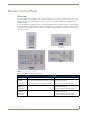
Novara AxLink KeyPads Novara AxLink KeyPads Overview Novara AxLink KeyPads can be used in both AxLink and Novara installations. Novara AxLink KeyPads feature a 4-pin AxLink connector and Status LED. Novara AxLink KeyPads feature one bi-directional RS-232 port 8 and 16 button layouts are available. Each button has LED feedback. SP-08-AX-US SP-16-AX-TR-US SP-08-AX-UK SP-08-AX-EU SP-16-AX-TR-UK FIG.
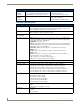
Novara AxLink KeyPads Product Specifications Novara AxLink KeyPads System Requirements: Novara AxLink KeyPads are only compatible with AMX NetLinx Central Controllers. Power Requirements: • SP-08: Min: 80mA / Max: 130mA @ 12 VDC Button Layout: • 8 and 16 button • SP-16: Min: 100mA / Max: 210mA @ 12 VDC • Blue, backlit buttons with controllable feedback Rear Panel Connectors: • 4-pin AxLink connector/Status LED • Power connectors Dimensions: • SP-08-AX-US: 4.685" x 2.913" x 1.034" (11.899 cm x 7.
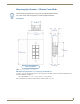
Novara AxLink KeyPads Mounting Specifications - 8-Button KeyPads Novara KeyPads are designed to fit in NEC-Compliant wall boxes only. These devices will not fit properly in non-NEC-Compliant wall boxes. SP-08-AX-US (4.701 cm) (2.702 cm) (2.415 cm) (2.956 cm) (2.669 cm) (7.399 cm) (11.899 cm) (6.799 cm) in inches - metric conversions shown in parenthesis FIG.
Novara AxLink KeyPads SP-08-AX-UK (6.799 cm) (2.702 cm) (2.415 cm) (2.669 cm) (2.956 cm) (14.698 cm) (8.600 cm) (4.701) in inches - metric conversions shown in parenthesis FIG.
Novara AxLink KeyPads SP-08-AX-EU (6.799 cm) (2.702 cm) (2.415 cm) (2.669 cm) (2.956 cm) (15.199 cm) (8.001 cm) (4.701) in inches - metric conversions shown in parenthesis FIG.
Novara AxLink KeyPads Mounting Specifications - 16-Button KeyPads US version Novara KeyPads are designed to fit in NEC-Compliant wall boxes only. These devices will not fit properly in non-NEC-Compliant wall boxes. SP-16-AX-TR-US (13.599 cm) (2.702 cm) (2.415 cm) (2.669 cm) (2.956 cm) (17.000 cm) (2.689 cm) (2.669 cm) (11.998 cm) in inches - metric conversions shown in parenthesis (6.799 cm) (2.415 cm) FIG.
Novara AxLink KeyPads SP-16-AX-TR-UK (13.599 cm) (2.415 cm) (2.669 cm) (22.999 cm) (11.000 cm) (2.702 cm) (6.799 cm) in inches - metric conversions shown in parenthesis FIG.
Novara AxLink KeyPads Wiring and Connections ControlPads - Rear Panel Connectors FIG. 21 shows the rear panel connectors of the Novara AxLink KeyPads, and indicates a typical installation: The rear panel connector layout is identical for all Novara AxLink KeyPads. Alternate Button Numbering DIP Switch NetLinx Master (AxLink port) AxLink Device Address DIP Switch AxLink Status LED FIG.
Novara AxLink KeyPads Daisy-Chaining KeyPads (AxLink only) To daisy chain the KeyPads via AxLink, both KeyPads should be connected to the AxLink, as shown in FIG. 23. Power Supply Power Supply GND AXM AXD FIG. 23 Daisy-Chaining KeyPads Use screened cable to link to units. Button Layout FIG.
Novara AxLink KeyPads Setting DIP Switches to Assign Alternate Button Numbering Use the 2-position DIP Switch on the rear panel of the KeyPads to specify alternate button numbers for each KeyPad, for cases in which you want to avoid having multiple KeyPads in the same system using the same button numbers. Multiple KeyPads are allowed to share identical button numbers. Alternate Button Numbering: 8-Button KeyPads The DIP Switch settings for 8-button KeyPads are described in FIG.
Novara AxLink KeyPads Setting the AxLink Address DIP Switch The AxLink Device Address DIP switch determines whether this KeyPad will function as an AxLink device or as a Serial device. If the DIP Switch is set to anything other than zero, this KeyPad will be assigned an AxLink device address based on the switch settings. Setting the AxLink Device Address 1. If connected, disconnect the power supply. 2. Locate the 8-position Device DIP switch on the rear panel.(FIG. 27). 3.
Button Labelling Button Labelling Overview Novara ControlPads, KeyPads and AxLink KeyPads come with a set of clear plastic Key Caps, which are designed to fit tightly over the pushbuttons, and allow you to place a label on each button according to the requirements of your particular installation. Novara ControlPads, KeyPads and AxLink KeyPads also come with a pre-printed acetate sheet with a range of 50 (pre-cut) button label inserts.
Button Labelling Key Cap - tilted so that the bottom of the Cap is placed on the bottom of the pushbutton first Clip At this point, do not allow the clips on the sides of the Key Cap to engage 1 Clip Pushbutton on keypad Press the top of the Key Cap down to engage both clips at once, securing the Key Cap to the pushbutton Once the clips are engaged, the Key Cap is secured to the pushbutton 2 3 FIG.
Button Labelling Removing/Replacing Button Labels The button labels on Novara keypads are acetate inserts that fit inside the Key Caps installed on the pushbuttons. In order to change the inserts, the key caps need to be removed.
Button Labelling 6. Carefully pull the bottom circuit board straight up and off the standoffs. The bottom board has the pushbuttons on the reverse side. Be careful not to damage the buttons when removing the board. Note the orientation of the board - it must be oriented in the same direction when replaced. The top of the is indicated by an UP arrow at the top center of the board. The bottom is indicated by the AMX logo (FIG. 33).
Button Labelling Verify that the vertical orientation of the Button Label is correct relative to the Novara keypad. Align the Key Cap with the target pushbutton, and gently push the Key Cap down over the pushbutton. Once seated properly on the pushbutton, the Key Cap will snap into place. Re-Assembling the Keypad Follow the steps in reverse to re-assemble the keypad. Take care of the following: Be certain that the circuit boards are oriented correctly (see FIG.
Button Labelling Exploded View - 16-Button US/UK/EU Version FIG.
AMX Novara DCS1000 Device Configuration Software AMX Novara DCS1000 Device Configuration Software Installing the AMX Novara DCS1000 Application 1. Download the AMX Novara DCS1000 installation file from www.amx.com (go to the Products page and search for DCS1000). 2. Double-click the installation file to launch the AMX DCS1000 Setup Wizard (FIG. 39). Click Next to proceed. FIG. 39 AMX DCS1000 Setup Wizard 3. Read the License Agreement (FIG.
AMX Novara DCS1000 Device Configuration Software FIG. 41 AMX DCS1000 Standard Installation 5. In the Installation Complete dialog, click Close to finish (FIG. 42). FIG. 42 Installation Complete dialog Launching AMX Novara DCS1000 Assuming you followed the default installation procedures, launch the AMX Novara DCS1000 application by doubleclicking the AMX Novara DCS1000 program icon on your desktop (FIG. 43). FIG.
AMX Novara DCS1000 Device Configuration Software Overview Novara ControlPads and KeyPads are configured using the AMX Novara DCS1000 software application, available for download from www.amx.com (FIG. 44). Menu Bar Command Bar System window Script window FIG.
AMX Novara DCS1000 Device Configuration Software Specifying Button Feedback A button LED has 3 possible states: On, Off and Flash. Use the Add Panel Feedback options to assign feedback to a selected button. Buttons can be assigned to a group where only one LED of the group may be on at any time. Adding Feedback to a Button Script (Example) 1. Select a button to configure from the System window (FIG. 46). FIG. 46 System window - Button 1 selected 2.
AMX Novara DCS1000 Device Configuration Software FIG. 48 Event Script window - Event 1 5. With button 2 selected, select Flash from the Select Button Feedback drop-down menu, and click on Add To Script add this feedback to the script. The Event Script will now show Event 2 as Button 2 Feedback: Flash (FIG. 49). FIG. 49 Event Script window - Event 2 6. Download the program to the ControlPad - see the Downloading the Program to the ControlPad section on page 33. 7.
AMX Novara DCS1000 Device Configuration Software 2. Select Button 1 in the System window (see FIG. 46 on page 34). 3. Click on Add Panel Feedback to invoke the Select Button Feedback window (FIG. 47 on page 34). 4. From the Select Action drop-down menu, select On/ Group Off, and click Group1 under Add To Group (as shown in FIG. 51). Repeat for Buttons 2 to 4. 5. Select Button 5, click on Add Panel Feedback, select On/ Group Off, and click on Group 2 (FIG. 52). FIG.
AMX Novara DCS1000 Device Configuration Software 2. Click Add Time Delay to invoke the Set Time Delay window (FIG. 54). FIG. 54 Set Time Delay window 3. Use the left/right arrow buttons to specify a time period. Click the arrows on the Hours field to adjust hours up/down, in one-hour increments. Click the arrows on the Minutes field to adjust minutes up/down, in one-minute increments. Click the arrows on the Seconds field to adjust seconds up/down, in one-half second increments.
AMX Novara DCS1000 Device Configuration Software RS232 Library files use the file extension *PRR. Adding a RS232 Command to an Event 1. Select the device to control from the Select Device drop-down menu. 2. Select the desired function from the Select Function drop-down menu. 3. Select the desired action from the Select Action drop-down menu. Action options include: Send String Once will send the command string one time only. Select Send No. allows you to send a command up to 50 times.
AMX Novara DCS1000 Device Configuration Software Viewing RS232 Libraries To view the RS232 libraries, open the RS232 window then click the View RS232 Library button to open the AMX RS232 Library dialog (FIG. 61).
AMX Novara DCS1000 Device Configuration Software New Device name New Function name Save Edit Copy Functions FIG. 63 AMX RS232 Library dialog (for a new device) 3. Enter a Function (in the Enter Function field). 4. Use the Bytes drop-down menus to enter the command string. 5. Specify the Device Protocol settings. 6. Click the Save Edit button (in the Edit options). Adding a New RS232 Function to a Device 1. Click the Add New Function Command Bar button (see FIG. 57 on page 37).
AMX Novara DCS1000 Device Configuration Software 3. The Device should then respond to the command sent. Creating a Test Serial Cable To connect to a Device to the PC a test cable can be made as follows: PC Serial Port (female D9 connector) Pin 3 to Device (RX) / Pin 5 to Device (Gnd) For testing through panel ports connect the Serial Programming Cable to the PC and to the panel’s Program Port. Verifying RS232 Commands To check a command from a Panel Port use the Verify RS232 Commands dialog (FIG. 65).
AMX Novara DCS1000 Device Configuration Software Novara IR Library files use the file extension *PLR. Adding an IR Command to an Event 1. Select the device to control from the Select Device drop-down menu. 2. Select the desired function from the Select Function drop-down menu. 3. Select the desired action from the Select Action drop-down menu. Action options include: Send IR Pulse sends the IR function 4 times only. IR Pulse No.
AMX Novara DCS1000 Device Configuration Software The options in this dialog allow you to create a new IR Device Library, as well as Edit or Add Functions to existing IR Libraries. Loading an Existing IR Library 1. Click File > Open. This invokes the Open dialog. 2. Select an IR Library (Data) file. Novara IR Library (Data) files use the file extension *PLR. It is recommended that all IR functions are tested before being written into program scripts (see the Testing IR Functions section on page 50).
AMX Novara DCS1000 Device Configuration Software FIG. 70 AMX IR Library dialog - showing a converted IRL file Downloading IR Files From www.AMX.com As a registered AMX Dealer, you can download AMX IR Library files directly from the Partners page of the www.amx.com website, as described below. You must log into the website as a Dealer in order to access these files. 1. Click the Partners link at the top of the main www.amx.com website to access the AMX Device Discovery Partners page (FIG. 71). FIG.
AMX Novara DCS1000 Device Configuration Software FIG. 72 www.amx.com - Search Devices page 3. Fill in the search fields with as much information as you can provide for the device for which you need an IR file. All search boxes use implied wild cards. For example, entering 'son' in the Manufacturer box will return Sonance, Sonic Blue, Sonic Foundry and Sony. 4. In the Control Method drop-down, select IR (FIG. 73). FIG. 73 Control Method drop-down menu 5. Click Search.
AMX Novara DCS1000 Device Configuration Software FIG. 74 Search results 6. Click IR in the Control Method column of the search results list to access the Device Model Details dialog for the selected device (FIG. 75). FIG. 75 Device Model Details dialog (IR Control Method) 7. In the left-hand menu bar under Model Control Method > IR, select Downloads to access the File(s) available for download for the selected device / control method (FIG. 76).
AMX Novara DCS1000 Device Configuration Software FIG. 76 Device Model Details dialog (Files Available for Download) 8. Click the file icon to download a file in the File(s) available for download list. Creating New IR Libraries Using an IRIS IR/Serial Data Capture Device The IRIS (FG5448) is a stand-alone, self-contained unit used to capture IR or wired function signals from a hand controller.
AMX Novara DCS1000 Device Configuration Software FIG. 79 AMX IR Library dialog - Learn New Functions fields 6. Connect the IRIS to your PC: a. Connect an RS-232 cable to the DB-9 connector on the IRIS unit and an RS-232 port on your PC. b. Set the baud rate in the IRIS unit to match the PC baud rate. c. Then, connect the 12 VDC or 12 VAC power supply to the 12 VDC connector on the IRIS unit. d. The READY LED lights and 01 appears in the display. 7. Enter a function name in the Enter Function text field.
AMX Novara DCS1000 Device Configuration Software FIG. 80 AMX Library Files dialog - Hex data import and conversion options 2. Enter the name of the function that you want to import, in the Enter Function text field. 3. Copy and paste the appropriate Hex code for this function in the Import Data text field (FIG. 81). FIG. 81 AMX Library Files dialog - Hex data entered The data should be entered without any extra symbols.
AMX Novara DCS1000 Device Configuration Software 5. In the Edit Options window of the AMX Library Files dialog, click Import Hex File to access the Hex data import and conversion options (FIG. 80). FIG. 83 AMX Library Files dialog - Hex data import and conversion options 6. Enter the name of the function that you want to import, in the Enter Function text field. 7.
AMX Novara DCS1000 Device Configuration Software FIG. 85 AMX Library Files dialog - Edit IR Data FIG. 86 AMX Library Files dialog - decreasing Frequency and Pulses/Bit values Alternatively, use the Auto Tune feature to transmit a range of frequencies one at a time: Click Auto Tune and wait to see if the device responds. If not, click Auto Tune again. Repeat until the device responds.
AMX Novara DCS1000 Device Configuration Software 1. Choose a button to configure and select Button > Toggle. This invokes the Toggle window (FIG. 88): FIG. 88 Toggle window 2. Click on the Enable checkbox. 3. Select the number of toggle presses required for the button (2, 3, or 4). 4. Note that initially the Toggle window is set to configure the first press of the button. Program the script as normal for the first button press. 5. Next select Program 2nd Press from the drop-down menu. 6.
AMX Novara DCS1000 Device Configuration Software FIG. 91 Script for Bank X2 (VCR Play) 5. Select X3 from the Assign To Bank drop-down menu and write a script for a CD player (FIG. 92). FIG. 92 Script for Bank X3 (CD Play) 6. Select X4 from the Assign To Bank drop-down menu and write a script for a tuner (FIG. 93). FIG. 93 Script for Bank X4 (Tuner On) 7.
AMX Novara DCS1000 Device Configuration Software FIG. 94 Displaying the Bank Enable options 3. Write a script for Button 5 and include Bank Enable X1 (FIG. 95). FIG. 95 Button 5 script, with Enable X1 Bank selected 4. Select Button 6 (in the System window) to program. This would be the VCR select button. 5. Write a Script for Button 6 and include Enable Bank X2 (FIG. 96). FIG. 96 Button 6 script, with Enable X2 Bank selected 6. Select button 7 which would be the CD select button. 7.
AMX Novara DCS1000 Device Configuration Software FIG. 97 Button 7 script, with Enable X3 Bank selected 8. Select button 8 (in the System window) to program. 9. Write a script for the Tuner select button including enable Bank X4 in the script (FIG. 98). FIG. 98 Button 8 script, with Enable X4 Bank selected The controlpad will now act in the following way. When Button 5 is pressed this will activate Bank X1. This means that whenever any button is pressed that is Bank X assigned the X1 script will run.
AMX Novara DCS1000 Device Configuration Software FIG. 99 Button 1 - selected to configure 2. In the menu bar, select Button > Bank assign. This invokes the Bank Assign options (FIG. 100): FIG. 100 Button > Bank assign 3. Select Bank X to enable the button press drop-down menu. 4. Select X1 from the Button Press drop-down menu (FIG. 101): Button Press drop-down menu FIG. 101 Assign to Bank X, X1 selected 5. Click the Add IR Function button in the Command Bar. 6.
AMX Novara DCS1000 Device Configuration Software 10. Select the appropriate RS232 Library for the device manufacturer (via the Change Library button), and select the desired device (from the Select Device drop-down menu). In this example, we’ll select the Sony VPL PX11 LCD Projector. 11. Choose the "Volume Down" command (in the Select Function drop-down menu) and click Add To Script to add it to the Event Script (FIG. 103): FIG.
AMX Novara DCS1000 Device Configuration Software FIG. 105 Button 3 - Button Bank X1 Enabled 15. Select Button 4 to configure (FIG. 106): FIG. 106 Button 4 selected to configure 16. Click on Enable a Bank in the Command Bar; select X2 and Add to Script (FIG. 107). FIG. 107 Button 4 - Button Bank X2 Enabled 17. Download the program to the ControlPad (via the Program menu bar item).
AMX Novara DCS1000 Device Configuration Software When Button 3 is pressed Buttons 1 and 2 will operate Volume Up/Down on the Sony PX32 Projector. When Button 4 is pressed Buttons 1 and 2 will operate Volume Up/Down on the Sony VPL PX11 LCD Projector. Advance Toggle The Advance Toggle feature allows a button to skip toggles. For example, a button is configured to toggle a Device on and off, and the first press turns the Device on.
AMX Novara DCS1000 Device Configuration Software Start Up A script can be written for button events to execute when the ControlPad is powered up: 1. From the Ancillary options (in the System window), select Start Up (FIG. 110): FIG. 110 Ancillary options - Start Up 2. This invokes the Program Start Up Events (Event Script) window (FIG. 111): FIG. 111 Program Start Up Events (Event Script) window 3.
AMX Novara DCS1000 Device Configuration Software 1. From the Ancillary options (in the System window), select Time Out (FIG. 114): FIG. 114 Ancillary options - Time Out 2. This invokes the Time Out window (FIG. 115): FIG. 115 Time Out window 3. Use the arrows on the Hours and Minutes fields to set a time for Time Period 1. 4. Write a script, as usual. When the panel is configured and a button press is not detected within the time period then the script will execute.
AMX Novara DCS1000 Device Configuration Software 3. Click Program. The programming window will appear. All the buttons on the Panel will illuminate and the program will download. When the download has completed the buttons will dim and a message will appear ‘Download Complete'. If an error occurs check the following: Cable is correctly connected Shut down any other programs running on the PC. If problem persists power down the Panel, hold in buttons 2 and 6 and re-power.
Control Strings for AxLink Control Strings for AxLink Available Control Strings The Novara AxLink keypads require the Control Commands to be sent as SEND_STRING. Available Control Strings Command Function BL=xx Set Backlight level • xx = 00-99 NOTE: numbers must be listed in format given, with single numbers prefaced with "0". MB=xx Set Max Brightness • xx = 00-99 NOTE: numbers must be listed in format given, with single numbers prefaced with "0".
Control Strings for AxLink 64 Novara ControlPads & KeyPads
AMX Novara DCS1000 Device Configuration Software Novara ControlPads & KeyPads 65
AMX. All rights reserved. AMX and the AMX logo are registered trademarks of AMX. AMX reserves the right to alter specifications without notice at any time. ©2014 1/14 It’s Your World - Take Control™ 3000 RESEARCH DRIVE, RICHARDSON, TX 75082 USA • 800.222.0193 • 469.624.8000 • 469-624-7153 fax • 800.932.6993 technical support • www.amx.