SERVO-DRIVESYSTEM General Manual Ver.
Title Type of documentation Internal code Model Version Software Electronic document Headquarters Servo-Drive System Description, Installation and setup of motors and digital drives. 04754001 MAN REGUL (IN) 0002 Version 04.01 D_DDS.pdf FAGOR AUTOMATION S.COOP. Bº San Andrés s/n, Apdo. 144 E-20500 ARRASATE-MONDRAGON www.fagorautomation.mcc.es info@fagorautomation.es Service Dept. Telephone 34-943-771118 The information described in this manual may be subject to changes due to technical modifications.
Evolution Version items 9702 First version 9707 PS-65, RM-15, CM-60, APS24, AXD3.., y SPD3.. PowerPro 110A, new motors FXM. 9802 Compact 8,25, 50,75, DDS PROGRAM MOD. Software 02.xx: Halt signal via digital input. Range expansion, (C axis) SERCOS interface. (connection and parameters) 9810 Software 03.xx: Sincoder feedback (E1). Motor identification at the encoder. Description of the XPS. Emergency ramps. Current filter. Sercos interface (servo system adjustment).
Selection RELATED DOCUMENTATION Fagor Motors and Drives Ordering Handbook Description Installation an setup This is your document.
General Index pg. SM. SM.1 SM.2 SM.3 SM.4 SM.5 SM.5.1 SM.5.2 SM.5.2.1 SM.5.2.2 SM.6 SM.7 SM.8 SM.9 AM. AM.1 AM.2 AM.3 AM.4 AM.5 AM.6 AM.7 AM.8 AM.8.1 AM.8.2 AM.8.3 AM.9 AM.9.1 AM.9.2 AM.9.3 AM.10 AM.10.1 AM.10.2 AM.10.3 AM.10.4 AM.10.5 AM.11 AM.12 AM.13 AM.13.1 AM.14 AM.15 EM. EM.1 EM.1.1 EM.1.2 EM.1.3 EM.1.3.1 EM.1.3.2 EM.1.3.3 EM.1.3.4 FXM SERIES SYNCHRONOUS MOTORS ........................................................... SM - 1 GENERAL CHARACTERISTICS ................................................
EM.2 EM.2.1 EM.2.1.1 EM.2.2 EM.2.3 EM.2.3.1 EM.3 EM.3.1 EM.3.2 EM.3.3 EM.3.3.1 EM.3.3.2 EM.4 EM.4.1 EM.4.2 EM.4.3 EM.4.3.1 EM.4.4 EM.4.4.1 EM.4.4.2 EM.4.5 EM.4.6 EM.4.7 EM.4.7.1 EM.4.7.2 EM.4.7.3 EM.4.8 EM.5 EM.6 EM.7 EM.8 EM.9 EM.9.1 EM.10 EM.11 EM.12 EM.13 IN. IN.1 IN.1.1 IN.2 IN.2.1 IN.2.2 IN.2.3 IN.2.4 IN.3 IN.3.1 IN.3.1.1 IN.3.1.2 IN.3.1.3 IN.3.1.4 IN.3.1.5 IN.3.1.6 IN.3.2 IN.3.2.1 IN.3.3 IN.4 IN.4.1 MODULAR DRIVE (AXES AND SPINDLE) ...................................................................
IN.4.2 IN.5 IN.6 IN.7 IN.7.1 IN.7.2 IN.7.3 IN.7.4 IN.7.4 IN.7.5 IN.8 IN.9 REC RESOLVER CONNECTION .................................................................................. IN - 18 BRAKE CONTROL ........................................................................................................ IN - 19 CONTROL POWER SUPPLY FOR THE MODULES ......................................................... IN - 20 CONTROL AND COMMUNICATION SIGNALS ..........................................................
AP. AP.1 AP.1.1 AP.1.1.1 AP.1.1.1.1 AP.1.1.1.2 AP.1.1.2 AP.1.1.2.1 AP.1.1.2.2 AP.1.1.2.3 AP.1.2 AP.1.3 AP.2 AP.3 AP.3.1 AP.3.1.1 AP.3.1.2 AP.3.2 AP.3.2.1 AP.3.2.2 AP.3.2.3 AP.3.3 AP.4 AP.4.1 AP.4.2 AP.4.3 AP.5 AP.6 AP.7 AP.8 AP.9 DS. DS.1 DS.1.1 DS.1.2 DS.1.3 DS.1.4 DS.2 DS.2.1 DS.2.1.1 DS.2.1.2 DS.2.2 DS.2.3 DS.2.4 DS.3 DS.4 DS.5 APPLICATIONS ......................................................................................................... AP - 1 SERCOS CONNECTION WITH THE 8050/55 CNC ............
DECLARATION OF CONFORMITY Manufacturer: Fagor Automation, S. Coop. Barrio de San Andrés s/n, C.P. 20500, Mondragón -Guipúzcoa- (SPAIN) We hereby declare, under our responsibility that the product: FAGOR Servo Drive System Consisting of the following modules and accessories: Power Supplies: XPS-25, XPS-65, PS-25A, PS-25B, PS-65A y APS 24 Modular Drives: AXD/SPD 1.08, 1.15, 1.25, 1.35, 2.50, 2.75, 3.100, 3.150 Compact Drives: ACD/SCD 1.08, 1.15, 1.25, 2.50, 2.
WARRANTY TERMS INITIAL WARRANTY All products manufactured or marketed by FAGOR carry a 12-month warranty for the end user. In order to prevent the possibility of having the time period from the time a product leaves our warehouse until the end user actually receives it run against this 12-month warranty, the OEM or distributor must communicate to FAGOR the destination, identification and installation date of the machine by filling out the Warranty Form that comes with each product.
SM. FXM SERIES SYNCHRONOUS MOTORS FXM series Fagor synchronous servo motors are AC Brushless, with permanent magnets. These motors are designed to work with Fagor servo drives. They are ideal to control feed and positioning axes in machine-tool applications as well as on material handling applications, textile machinery, printing, robotics, etc. and in any application requiring great positioning accuracy.
SM.1 GENERAL CHARACTERISTICS Standard characteristics of FXM motors: Excitation Permanent rare earth magnets (SmCo) Temperature sensor Thermistor Shaft end Cylindrical with keyway.
SM.2 ELECTRICAL CHARACTERISTICS Torque/speed characteristic of synchronous motors: Par -NmLímite de desmagnetización Mp -Par de pico del motor-Par de pico limitado por el Regulador- Limitación por tensión 2 Mo -Par a rotor parado- Limitación debida a la máxima corriente ofrecida por el Regulador. Mn -Par nominal1 Velocidad -rpmnN -Velocidad nominal- 1 Work area for permanent duty cycle (S1). Limited by the motor stall torque and the torque at rated speed. 2 Work area for intermittent duty cycle.
nN -rpm2000 3000 4000 2000 3000 4000 2000 3000 4000 2000 3000 4000 2000 3000 4000 2000 3000 4000 2000 3000 4000 2000 3000 4000 1200 2000 3000 4000 1200 2000 3000 4000 1200 2000 3000 4000 Imax -A1,3 2,0 2,5 2,5 4,0 5,0 4,0 5,5 7,5 5,0 8,0 10,0 4,0 5,5 7,5 7,5 11,5 15,5 11,5 17,5 23,0 15,5 23,5 31,0 12,0 20,0 30,0 40,0 16,0 27,5 40,5 51,0 20,0 34,0 51,0 66,5 tac -ms11,6 17,4 23,2 9,3 14,0 18,7 10,8 16,2 21,6 9,7 14,5 19,3 9,4 14,1 18,8 7,9 11,9 15,9 7,6 11,4 15,2 7,4 11,1 14,8 5,8 9,6 14,4 19,3 6,8 11,4 17,
(*) Mo, Io: Mp, Imax: nN: SM - 5 Pow: KT: tac: L, R: J: P: tac -ms11,9 19,8 29,6 39,5 11,6 19,3 29,0 38,6 12,6 20,9 31,4 41,9 12,2 20,3 30,4 40,6 13,0 21,6 32,4 43,2 13,0 21,7 32,6 43,5 L R J -mHr- Ohms Kg.
* * * * * * ** * * ** * ** ** Ver.
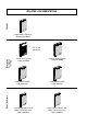
SM.3 DIMENSIONS Synchronous Motors Ver.
SM - 8 Synchronous Motors Ver.
Synchronous Motors Ver.
Detail on the internal thread of the shaft. Detail on power and feedback connectors for FXM motors. - Power connector for motors with a rated current smaller than 23 Amp. Feedback connector via Resolver ROC 9. - Power connector for motors with a rated current greater than 23 Amp. Feedback connector via Encoder EOC 12. - Power connector for motors with a rated current greater than 46 Amp. - Power connector for optional fan on FXM5 and FXM7 motors SM - 10 Synchronous Motors Ver.
Synchronous Motors Ver.
SM.4 BRAKE CHARACTERISTICS FXM motors have a brake that acts by friction against the shaft. It is used to hold the motor. It MUST NOT be used to stop the motor when it is turning. Torque Maximum RPM Power On/Off Delay Unlocking voltage margin Inertia Nm (in.lb) rpm W (HP) ms Vdc Kg.cm2 (lb.in2) Kg (lbf) FXM 1 2.5 (22.12) 10000 12 (0.016) 7/5 0,38 (0.13) 0,3 (0.66) FXM 3 5 (44.25) 8000 16 (0.021) 15/7 1,06 (0.36) 0,6 (1.32) FXM 5 12 (106.2) 6000 18 (0.024) 30/13 3,6 (1.
SM.5.2 FEEDBACK CONNECTOR Depending on the type of feedback integrated into the motor (encoder or resolver) the connector will be either a 12-pin or a 9-pin. SM.5.2.1 ENCODER FEEDBACK CONNECTOR It is a 12-pin male Conney type connector which meets the IP65 sealing standard. The various encoder types available use this connector. The cable necessary to connect this connector with the drive module is the one referred to as EEC. Chapter IN describes this cable in detail.
SM.5.2.2 RESOLVER FEEDBACK CONNECTOR It is a 9-pin male Conney type connector which meets the IP65 sealing standard. Connector and signals (front view): Pin RESOLVER 1 8 9 2 7 6 3 4 5 Signal 1 S1 2 S3 3 S4 4 S2 5 R1 6 R2 7 TEMP 8 TEMP 9 CHASSIS Function Cosinewave signal provided by the Resolver. Sinewave signal provided by the Resolver. Sinewave signal for the excitation of the rotating transformer primary.
SM.6 INSTALLATION AND MOUNTING CONDITIONS Before installing it onto the machine, the anti-rust paint should be removed from the rotor shaft and the flange. The motor admits the B5, V1 and V3 mounting methods. The ambient conditions recommended for the motor are the ones indicated in the general characteristics bearing in mind that: B5 V1 V3 It must always be in a dry and clean place. Mounted so it is easily inspected, cleaned and maintained.
SM.8 IDENTIFICATION BOARD Example: Fagor Automation S. Coop. (Spain) AC BRUSHLESS SERVOMOTOR SM.9 Type FXM 32.20A.R0.000 Ver.: 00 SN F170000.01 Mo 3.9 Nm Io 1.5 Amp Mmax 19.5 Nm Imax 7.5 Amp BRAKE 24 VDC / 20W Nominal Speed: B.E.M.F.: 320 v IP64 W: 12 kg 2000 rpm Iso.cl Bal.cl F N REGISTRATION NUMBERS FOR FXM MOTORS Many of the Drive's Software parameters are directly related to the characteristics of the motor it governs.
AM. SPM ASYNCHRONOUS MOTORS Fagor asynchronous motors, also called induction motors, are designed to work on machinetool spindles. SPM motors are asynchronous "squirrel cage" motors and are especially designed to work with Fagor drives. To control the axes of a machine, the FXM servomotors must be used. They are described in the SM chapter of this manual. There is a wide range of motors available: from 2.2 Kw to 37 Kw in S1. The particular characteristics of each motor are described on the following pages.
AM - 2 AM.2 ELECTRICAL CHARACTERISTICS Electric characteristics table of the new SPMxxx.xx.xxxxx.
Asynchronous Motors SPMxxx.xx.xxxxx.0 motors differ from these only on the values of their current: Ver.
AM - 4 AM.4 BRAKE CHARACTERISTICS (OPTIONAL) SPM 90L Power supply Power Continuous torque Inertia AM.5 W Nm Kg.m2 SPM 90P 16 10 0.00011 SPM 100LBE SPM 112ME 22 30 0.0003 SPM 112LE SPM 112XE 220 SPM 132L SPM 132X 25 50 0.00057 SPM 132XL SPM 160M SPM 160L 29 150 0.
AM.6 POWER AND TORQUE CHARACTERISTICS The following sections show the electrical and mechanical characteristics of power and torque for each SPM motor. The Power-Speed curves are shown for the S1 and S6 cycles at 40%. Over the curves for each motor, the powers that may be reached with the various Fagor Drives are also indicated. This is very useful for selecting the right drive for each motor and application. Very important: It is assumed that the drive system is powered at 380 Vac from Mains.
SPM 90L Rated power S1 Rated power S6-40% Rated Torque S1 Rated Torque S6-40% Rated current S1 Rated current S6-40% Rated speed Maximum speed Maximum speed (*) Inertia Weight kW kW Nm Nm Arms Arms rpm rpm rpm Kg·m2 Kg SPM 90L 2,2 3,3 14 21 7,78 11,7 1500 9000 -0,0035 19,2 SPM 90L .1 6 1.25 Drive 1.25 Drive S6-40% 1.15 Drive S1 power (kw) 5 4 S6-40% 1.
SPM 100LBE Rated power S1 Rated power S6-40% Rated Torque S1 Rated Torque S6-40% Rated current S1 Rated current S6-40% Rated speed Maximum speed Maximum speed (*) Inertia Weight kW kW Nm Nm Arms Arms rpm rpm rpm Kg·m2 Kg SPM 100LBE 4 6 25,5 38 13,6 20,4 1500 9000 -0,0061 35,3 power (kw) SPM 100LBE .1 9 8 7 6 5 4 3 2 1 1.35 Drive S6-40% 1.
SPM 112LE Rated power S1 Rated power S6-40% Rated Torque S1 Rated Torque S6-40% Rated current S1 Rated current S6-40% Rated speed Maximum speed Maximum speed (*) Inertia Weight kW kW Nm Nm Arms Arms rpm rpm rpm Kg·m2 Kg SPM 112LE 7,5 11 47,7 70 24 34,5 1500 7500 9000 0,014 53 SPM 112LE .1 14 power (kw) 12 2.50 Drive S6-40% 1.
SPM 132L Rated power S1 Rated power S6-40% Rated Torque S1 Rated Torque S6-40% Rated current S1 Rated current S6-40% Rated speed Maximum speed Maximum speed (*) Inertia Weight kW kW Nm Nm Arms Arms rpm rpm rpm Kg·m2 Kg SPM 132L 15 22 95,5 140 47,7 70 1500 7500 9000 0,062 108 SPM 132L .1 30 3.100 Drive S6-40% 2.
SPM 132XL Rated power S1 Rated power S6-40% Rated Torque S1 Rated Torque S6-40% Rated current S1 Rated current S6-40% Rated speed Maximum speed Maximum speed (*) Inertia Weight kW kW Nm Nm Arms Arms rpm rpm rpm Kg·m2 Kg SPM 132XL 22 28 140 178 62,3 79,3 1500 7500 9000 0,07 119 SPM 132XL .1 power (kw) 40 3.150 Drive 3.
SPM160L Rated power S1 Rated power S6-40% Rated Torque S1 Rated Torque S6-40% Rated current S1 Rated current S6-40% Rated speed Maximum speed Maximum speed (*) Inertia Weight kW kW Nm Nm Arms Arms rpm rpm rpm Kg·m2 Kg SPM 160L 30 45 191 286 76 114 1500 6300 9000 0,17 196 SPM 160L .0 power (kw) 50 S6-40% 3.150 Drive 3.
Asynchronous Motors 19 (0.75) 40 (1.57) 50 (1.97) M8 7 (0.27) 3.5 (0.14) Flange Centering Tolerance: j6 84.5 (3.3) 24 (0.94) 8 (0.31) SHAFT 38.5 (1.49) 27 (1.06) Tolerance: j6 Brake: + 70 (2.75) 420 (16.53) 125 (4.92) 23.5 (0.92) 135 (5.31) 268 (10.55) 56 (2.2) 43 (1.69) 79 (3.11) 152 (5.98) 40 (1.57) 89 (3.5) 240.5 (9.45) 5 (0.19) 4 x ø 11.5 ø 130 (5.12) AM - 12 0 20 7) .8 (7 1/2"G SPM 90 L 160 (6.3) 140 (5.51) ø 9 (0.35) 1 (6. 65 49 ) 84 (3.3) 160 (6.3) 35 (1.
Ver. 0002 22 (0.86) 50 (1.97) 60 (2.36) 3.5 (0.14) Flange Centering Tolerance: j6 M10 7 (0.27) 56 (2.2) 26.5 (1.04) 135 (5.31) 28 (1.1) 8 (0.31) SHAFT 345 (13.58) 31 (1.22) Tolerance: j6 Brake: + 75 (2.95) 497 (19.56) 203 (7.99) - 215 (8.46) 23.5 (0.92) 43 (1.69) 150.5 (5.92) 89 (3.5) 152 (5.98) 40 (1.57) 79 (3.11) 5 (0.19) 160 (6.3) 140 (5.51) ø 9 (0.35) 1 (6. 65 49 ) 84 (3.3) 0 20 7) .8 (7 1/2"G SPM 90 P 4 x ø 11.5 ø 130 (5.12) 306.5 (12.06) 160 (6.3) 35 (1.37) 80 (3.
Asynchronous Motors 22 (0.86) 50 (1.97) 60 (2.36) 12 (0.47) M10 7 (0.27) 28 (1.1) 31 (1.22) Tolerance: j6 Brake: + 65 (2.55) SHAFT 8 (0.31) 54 (2.12) 514 (20.23) 473 (18.62) 140 (5.51) 63 (2.48) 4 (0.15) 60 (2.36) Flange Centering Tolerance: j6 24 (0.94) 122 (4.8) 89 (3.5) 156 (6.14) 4 x ø14 2 (9 50 .8 4) 160 (6.3) 200 (7.87) SPM 100 LBE ø180 (7.08) 13 (0.51) 297 (11.69) 2 (8 15 .4 6) 10.5 (0.41) Pg21 100 (3.94) 100 (3.94) 135 (5.31) 61 (2.4) ø AM - 14 Ver.
22 (0.86) 50 (1.96) 60 (2.36) M10 28 (1.1) 8 (0.31) SHAFT 70 (2.75) 29 (1.14) 7 (0.27) 60 (2.36) 4 (0.16) Flange Centering Tolerance: j6 11 (0.43) 138 (5.43) Pg21 51 (2.0) 31 (1.22) Tolerance: j6 Brake: + 70 (2.75) 518 (20.39) 477 (18.78) 140 (5.5) 321 (12.63) 61 (2.4) 122 (4.8) ø 12 (0.47) 301 (11.85) 4 x ø14 2 (8 15 .4 6) 224 (8.82) 190 (7.48) 122 (4.8) SPM 112 ME 180 (7.08) Ver. 0002 0 25 4) 8 (9. Pg21 112 (4.41) 112 (4.41) Asynchronous Motors AM - 15 285 (11.
Asynchronous Motors 28 (1.1) 70 (2.75) 80 (3.15) 80 (3.15) 4 (0.16) Flange Centering Tolerance: j6 M12 8 (0.31) 70 (2.75) 29 (1.14) 61 (2.4) 38 (1.49) 10 (0.39) SHAFT 391 (15.39) Brake: + 70 (2.75) 101 (3.97) Pg21 122 (4.8) 588 (23.15) 547 (21.53) 41 (1.61) Tolerance: k6 140 (5.51) ø 12 (0.47) 351 (13.82) 4 x ø14 2 (8 15 .4 6) 224 (8.82) 190 (7.48) 122 (4.8) SPM 112 LE 180 (7.08) 11 (0.43) 188 (7.4) 0 25 4) 8 (9. Pg21 112 (4.41) 112 (4.41) AM - 16 Ver. 0002 285 (11.
28 (1.1) 70 (2.75) 80 (3.15) 80 (3.15) 4 (0.16) Flange Centering Tolerance: j6 11 (0.43) 70 (2.75) 29 (1.14) M12 8 (0.31) 38 (1.49) 10 (0.39) SHAFT 501 (19.72) ø 12 (0.47) 41 (1.61) Tolerance: k6 106 (4.17) Pg21 122 (4.8) Brake: + 70 (2.75) 698 (27.48) 657 (25.86) 61 (2.4) 245 (9.64) 293 (11.53) 461 (18.14) 4 x ø14 2 (8 15 .4 6) 224 (8.82) 190 (7.48) 122 (4.8) SPM 112 XE 180 (7.08) Ver. 0002 0 25 4) 8 (9. Pg21 112 (4.41) 112 (4.41) Asynchronous Motors AM - 17 285 (11.
110 (4.33) 4 (0.16) Flange Centering Tolerance: j6 14 (0.55) Asynchronous Motors 36 (1.41) 100 (3.93) 110 (4.33) 89 (3.5) 26 (1.02) ø 12 (0.47) M16 1" GAS 42 (1.65) 12 (0.47) SHAFT 156 (6.14) 1/2" GAS 45 (1.77) Tolerance: k6 790 (31.1) Brake: + 75 (2.95) 750 (29.52) 332 (13.07) 8 (0.31) 72 (2.83) 321.5 (12.65) 89 (3.5) 219 (8.62) 40 (1.57) 4 x ø 14 ø 12 (0.47) 264 (10.39) 216 (8.5) 156 (6.14) SPM 132 L SPM 132 X SPM 132 XL ø 230 (9.05) 512 (20.16) (1 300 1. 81 ) 206 (8.
Ver. 0002 110 (4.33) 5 (0.19) Flange Centering Tolerance: h6 18 (0.7) 36 (1.41) 100 (3.93) 110 (4.33) 108 (4.25) 30 (1.18) ø 14 (0.55) 71 (2.79) M16 48 (1.88) 14 (0.55) SHAFT 51.5 (2.02) Tolerance: k6 Pg29 Brake: + 75 (2.95) 819 (32.24) 772 (30.39) 9 (0.35) 254 (10) Pg21 186 (7.32) 4 x ø 18 ø 14 (0.55) 0 35 78) . (13 320 (12.6) 254 (10) 171 (6.73) SPM 160 M 250 (9.84) Asynchronous Motors 230.5 (9.07) 160 (6.3) 242 (9.52) 466 (18.34) 0 30 81) . (11 AM - 19 390.5 (15.
110 (4.33) 5 (0.19) Flange Centering Tolerance: h6 Asynchronous Motors 36 (1.41) 100 (3.93) 110 (4.33) 108 (4.25) 30 (1.18) ø 14 (0.55) M16 9 (0.35) 48 (1.88) 14 (0.55) SHAFT 51.5 (2.02) Tolerance: k6 Brake: + 75 (2.95) 967 (38.07) 918 (36.14) 400 (15.75) 71 (2.79) Pg21 Pg29 186 (7.32) 4 x ø 18 ø 14 (0.55) 0 35 8) .7 (13 320 (12.6) 254 (10) 171 (6.73) SPM 160 L 250 (9.84) 18 (0.7) 388 (15.27) 612 (24.09) 230.5 (9.07) 160 (6.3) AM - 20 0 30 81) . (11 Ver. 0002 390.5 (15.
Flange Centering Tolerance: h6 110 (4.33) 5 (0.19) 16 (0.63) Ver. 0002 42 (1.65) 100 (3.93) 110 (4.33) 121 (4.76) 37 (1.45) ø 14 (0.55) 603 (23.74) Pg36 184 (7.24) 10 (0.39) M20 318 (12.52) 55 (2.16) 16 (0.63) SHAFT 891 (35.07) 848 (33.38) 279 (10.98) 537 (21.14) 59 (2.32) Tolerance: j6 300 (11.81) ø14 (0.55) 4 (15 00 .75 ) 360 (14.17) 279 (10.98) SPM 180 MA 4 x ø 18 253 (9.96) 350 7) .7 (13 100(3.94) 180 (7.08) 180 (7.08) Asynchronous Motors AM - 21 465 (18.
AM.8 CONNECTORS 1 2 1 3 AM.8.1 2 3 Terminal box for power and brake (option) connection. Encoder feedback connector Terminal box or connector for the fan (the 1 , 2 , 3 , name is not printed on the motor) POWER AND BRAKE CONNECTION It is done through an internal terminal box. * Power terminals. * Internal thermal switch contacts (Klixon 150°C (302°F)). * Brake contacts as an option. There is internal thermal switch as a protection against overtemperature.
AM.8.2 FEEDBACK CONNECTION. ENCODER It is done through a 12-pin male Conney connector which assures a sealing degree of IP65. The various available encoder models use this connector. The cable required to connect this connector with drive module is the one referred to as EEC. Chapter IN describes this cable in detail. Connector and signals (front view). Θ is the angular rotor position. ENCODER 9 1 2 3 10 12 11 4 AM.8.3 1V 8 7 REFCOS REFSIN 6 2.
AM.9 INSTALLING RECOMMENDATIONS The motor should be installed in a clean, dry and well ventilated place. It should be easily accessible for inspection and maintenance. There must be a gap between the armature of the motor and the structure of the machine NEVER SMALLER than 5 mm in order to avoid electromagnetic interference and transmission of vibration. Make sure that air circulates around the motor. Provide an unobstructed air entry and output for the fan. AM - 24 Asynchronous Motors Ver.
AM.9.1 VENTILATION SPM series motors carry an electric fan that generates a constant air flow regardless of the motor speed. That way, proper cooling is assured for any working condition. The motors can run at their rated current or peak current at low speeds without losing their specifications. The electric fan must be turned on before powering the motor and must never be stopped while the machine is on. Important: Make sure that the air taken in by the fan is always fresh, clean and dry.
AM.9.3 AMBIENT CONDITIONS Before mounting it onto the machine, the anti-rust paint should be removed from the rotor shaft and the flange. The environmental conditions recommended for the motor are the ones indicated in the general characteristics bearing in mind that: · · · · It must be located in a clean and dry place. Easily accessible for inspection, cleaning and maintenance. Free of corrosive ambient and explosive gasses or fluids.
AM.10.3 COUPLING THROUGH GEAR BOXES Refer to the "direct coupling" section and to any information provided by the manufacturer of the gear boxes. AM.10.4 BALANCING The rotor is dynamically balanced with the key inserted in the keyway. It is an "S" degree balancing and, upon request, an "SR" degree can be obtained. It is important that the pulley, half-joint or rack be dynamically balanced (without the key) before inserting them in the transmission shaft.
AM.12 BEARINGS The special bearings are the ball-bearing type, suitable for high speeds and lubricated with special greases resistant to high rotation and temperature conditions. The maximum theoretical life of the bearings is calculated in about 20,000 hours of continuous operation at 1500 rpm approx. For higher average rotation speeds, the life of the bearings varies as follows: 30 - 50% of nmax .– about 16,000 hours 50 - 60% of nmax .– about 12,000 hours 60 - 70% of nmax .
AM.13 MAINTENANCE INTERVALS First inspection: in normal cases and after about 500 hours of operation, at any rate within a year from start-up date. Check that the plate data are followed and there are no vibrations, noises, high temperatures or structural damages to the motor and accessories. Re-lubing of bearings: Fagor recomends the lube oil from KLUBER (ISOFLEX LDS 18 SPECIAL A). Depending on the type of bearing, dimensions, average speed and operating and temperature conditions.
AM.14 IDENTIFICATION BOARD The identification plate of each motor has the shape shown in the next figure. 3 Phase Fagor Automation S. Coop. (Spain) AC Induction Motor Type SPM 112LE.E1.00000.1 Rel. C SN 96L 1078 Year 1999 Hz 50 Vn 330 Vac S6 S1 Conn. Nm 47.7 Nm P 11 kW Pn 7.5 kW IP 54 Slip 55 rpm I 34.5 A In 24 A 53 kg I. cl F Speed Nn/Nmax 1500/7500 rpm W M V1/V5 B. cl S Magnetizing current 11.4 A Transducter type Stegman Resistance (ph/ph) 0.44 Ω Brake type Inductance (ph/ph) 5.
EM. ELECTRONIC MODULES The Fagor Servo-Drive System has a modular stackable design. It is connected directly to a three-phase mains of 50/60 Hz with a rated voltage between 380Vac-15% and 460Vac+10%. It supplies the motors with three-phase 380 Vac and variable frequency to control its speed. Depending on the user's needs, it may consists of the following elements: Power Supply Module. PS. Module in charge of converting the alternating current of mains into dc voltage for the drives.
EM - 2 Electronic Modules Ver.
Electronic Modules Ver.
EM - 4 Electronic Modules Ver.
EM.1 POWER SUPPLY MODULE They are directly connected to 380-460 Vac, 50/60 Hz Mains and provide a dc voltage output of about 600 Vdc depending on Mains power. This voltage supplies to the Drive Modules through what we call Power Bus. These Power Supplies also handle the energy excess accumulated at the Power Bus usually due to motor braking. We call them Non-regenerative Power Supplies when this excess of energy is dissipated as heat on certain electrical resistors.
EM.1.1 GENERAL CHARACTERISTICS OF THE NONREGENERATIVE POWER SUPPLIES PS-25A Module PS-65A Module Power supply (Vmains) Three-phase 50/60 Hz, with a voltage range between 380Vac -15%.
PS-25B Module Three-phase 50/60 Hz, with a voltage range between 380Vac -15%.
EM.1.2 GENERAL CHARACTERISTICS OF THE REGENERATIVE POWER SUPPLIES XPS-25 Module Power supply (Vmains) Mains power consumption Maximum connection cable section Three-phase 50/60 Hz, with a voltage range between 380Vac -15%. and 460Vac +10% 38 Amp -RMS- 100 Amp -RMS- 16 mm2 50 mm2 540 Vdc / 650 Vdc Voltage of the Power Bus. VBUS NOM Rated (peak) output current (*) Rated (peak) output power 45 Amp (100 Amp, 1 sec) 120 Amp (120 Amp, 1 sec) 25 kW (55 kW, 1 sec) 65 kW (108 kW, 1 sec) Vmains x 1.
EM.1.3 POWER SUPPLY CONNECTORS 1. Power connectors for Mains. 2. Power connectors for the external Ballast resistor. 3. Ground connector for the cable hose from Mains and intermodular Chassis connections. 4. Lamps indicating the status of the Main Power Supply. “FAULT”. When blinking, it indicates that one or several Mains phases are missing. “FAULT” on, it indicates an error specified at the display of the drives. "BALLAST" it comes on when the energy dissipating Ballast circuit is activated.
EM - 10 Electronic Modules Ver.
EM.1.3.1 POWER CONNECTORS OF THE POWER SUPPLIES Terminal strip for connection to Mains. From Mains R S T N RST phases may be connected in any sequence. Ready Made Cable MPC-4x...(mm2) The phases may be connected in any sequence. The ground connection of the cable shields is made from the vertical plate next to the terminal strip. PS-25A PS-25B XPS-25 8.1 1 4 10,16 1,5 10 12.1 2 16 Gap between terminals (mm) Max. tightening torque (Nm) Maximum Section (mm2) L1 L2 L3 PS-65A XPS-65 18.
If this jumper between "Ri" and "L+" is eliminated and no external resistor is connected, error 215 or 304 will be issued. In the case of the PS-25B module, the Power bus will not be loaded. The power supply carries a protection against over-temperatures which triggers error 301 when reaching 105°C (221°F). The power being dissipated by these resistors depends on the ambient temperature according to the following derating curves.
In the case of the PS-25B power supply, it will be enough to have all three phases of Mains The start process begins when the "FAULT" lamp stops blinking and it is over, the "DC BUS ON" lamp comes on. Before handling these leads, proceed in the following order: 1st Stop the motors. 2nd Disconnect the Mains voltage at the electrical cabinet. 3rd Wait, before handling these leads. The Power Supply module needs time to decrease the voltage of the Power Bus down to safe values (< 60Vdc).
EM.1.3.2 X1 CONNECTOR, INTERNAL BUS Interconnects all the elements of the Servo Drive System. All the modules powered with the same Power Supply must be connected to this Bus and it is required to run it. The Bus must not be disconnected while the system is running. A ribbon cable is provided with each module (Power Supply or Drive) for this connection. When using two Power Supply modules within the same Servo system, each group must carry its own internal Bus. EM.1.3.
Procedure to turn on the Power Supply module: 1. At the PS-xxA models. Supply 24 Vdc to the control circuits of the module through connector X2 (pins 9 and 10). 1. At the XPS and PS-25B. Apply power to the Auxiliary Power Supply from Mains through connector X3 (pins 2 and 3). These will power the control circuits of the module and provide 24 Vdc at connectors X4, X5 and X6. 2. The Power Supply module will check the system status. If not OK, it will turn on the red "FAULT" lamp.
EM.1.3.4 CONNECTORS X3, X4, X5, X6 (XPS AND PS-25B) All four connectors belong to the Auxiliary Power Supply. X3 receives power from Mains. It admits between 380 Vac and 460 Vac. This power supply generates 24 Vdc to feed the control circuits of the module itself. Also, up to 8 Amps of dc voltage are supplied through X4, X5 and X6 . These three connectors are identical and offer greater connecting flexibility. PS-25B XPS-25 XPS-65 X3 1 3 (Phoenix, 7.
EM.2 MODULAR DRIVE (AXES AND SPINDLE) There are modular drives specific for controlling axes (synchronous motors) and the spindle (asynchronous motors). This chapter is common to both models because their external characteristics: dimensions, connectors, etc. are the same. EM.2.1 GENERAL CHARACTERISTICS, MODULAR DRIVES EM.2.1.1 AXIS AND SPINDLE DRIVES Axis Drive (Synchronous Motors) AXD 1.08 AXD 1.15 AXD 1.25 AXD 1.35 AXD 2.50 AXD 2.75 AXD 3.100 AXD 3.
EM.2.2 DERATING OF THE MODULAR DRIVES The following graphs show the maximum rms current in continuous duty cycle that the various Drive modules can provide depending on ambient temperature. Axis drives: For a maximum time period of 0.5 seconds, and always in cycles longer than 10 seconds, they may output twice the current. The AXD 1.08 and AXD 1.15 models, maintain their best characteristics, indicated in the previous table, throughout the full temperature range, between 5 and 55°C (41 ºF and 131 ºF).
Spindle drives: The drive can output the indicated current in any duty cycle. Models SPD 1.08, SPD 1.15, SPD 1.25, SPD 2.50 and SPD 3.100, maintain their best characteristics, indicated in the previous table, throughout the full temperature range, between 5 and 55°C (41ºF and 131 ºF). Current S1 (Amp) SPD 1.35 28.5 27.6 50 (122) 55 (131) Current S1 (Amp) Current S1 (Amp) SPD 2.75 53 106 43 92 35 (95) Electronic Modules Ver. 0002 55 (131) °C (°F) °C (°F) SPD 3.
EM.2.3 CONNECTORS OF THE MODULAR DRIVE The next figure shows the elements appearing on the front plate of the modular drive: 1) 2) 3) 4) 5) Power connectors for motor connection. 2.5 Amp (F) / 250V Fast fuse. To protect the internal control circuits. Sercos Interface connectors. Status Display. Shows status information for the drive itself or the relevant code when there is an error. Power connectors at the bottom to power the Drive module.
EM.2.3.1 POWER CONNECTORS The upper connectors are for connecting the motor. The ground connection of the cable shields is made from the vertical plate next to the connectors. The bottom connectors correspond to the power bus input. The drive needs 456-800Vdc which can vary depending on the Mains voltage and the load. The power supply module is in charge supplying this voltage. 2 plates are supplied with each module for this connection and another one for connecting the chassis with each other.
EM.3 COMPACT DRIVE (AXES AND SPINDLE) The Fagor Compact Drive has its own power supply and it can be connected directly to Mains. Its behavior, functionality and parameters are the same as those of the Modular Drive. EM.3.1 GENERAL CHARACTERISTICS See the table on the next page, EM.3.2 DERATING, COMPACT DRIVES The following graphs show the maximum rms current in continuous duty cycle offered by the various compact drives depending on ambient temperature. Fagor ACD 2.
Axis Compact Drive ACD 1.08 (Note 1) ACD ACD ACD 1.15 1.25 2.50 Spindle Compact Drive ACD 2.75 Rated current (Amp) 4 7,5 12,5 25 37,5 Maximum peak current for 500ms in cycles longer than 10 seconds. 8 15 25 50 75 SCD 1.08 SCD 1.15 5,6 10,6 Maximum current in any duty (Note 3) (Note 2) SCD SCD 1.25 2.50 17,7 35,4 SCD 2.75 53 Three-phase mains 50/60 Hz, with a voltage range between 380Vac -15%. and 460Vac + 10% Power supply Internal power bus voltage.
EM.3.3 CONNECTORS OF THE COMPACT DRIVE The next diagram shows the elements appearing on the front plate of the Compact Drive: 1) 2) 3) 4) 5) Power connectors for motor and mains connection. Access to the power bus. Fuses to protect the internal control circuit. Two 1 Amp (T) / 500V slow fuses on the power supply lines. Sercos Interface connectors. Status Display. Shows the status information of the drive itself or the corresponding error code. Compact Drive Status Leds.
EM.3.3.1 POWER CONNECTORS They are used for connecting the compact drive to mains (L1, L2, L3) and to the motor (U, V, W). They also have the necessary terminals for connecting an external Ballast resistor. For the ACD1... and SCD1... type drives, this same upper connector gives access to the Power Bus (L+, L-). The ground connection of the cable shields is made from the vertical plate next to these connectors. The ACD2... and SCD2... provide the Bus via the lower connector like modular drives.
Before handling these terminals proceed as follows: 1st Disconnect the Mains voltage at the electrical cabinet. 2nd Wait before handling these terminals The module needs time to bring the voltage at the power bus down to safe values (< 60Vdc). The fact that the green “DC BUS ON” light is off does not mean that it is safe to handle the power bus. The discharge time depends on the number of elements connected to this Bus and it is approximately 4 minutes..
Configuration for external resistor R. ext ER EM.3.3.2 R. int ACD SCD Ri Re L+ L- R. int CONTROL L+ L- ACD SCD Ri Re L+ CONTROL L+ Configuration for internal resistor CONNECTOR X1 Compact Drives internally generate the 24Vdc necessary for the internal circuits. In regular operation, this voltage is obtained from the Power Bus and from mains when starting up the system. The mains energy necessary for start-up is supplied via this three-prong Phoenix connector.
EM.4 EM.4.1 ASPECTS COMMON TO BOTH MODULAR AND COMPACT STATUS DISPLAY During the module start up, in order to check that all the display segments are operating correctly, this display shows the following information: First, the display is seen completely off, and then it shows numbers 1, 2, 3 and 4 corresponding to the four initializing stages and, then, it will turn back off. Then, the version of the software used by the module is shown.
EM.4.2 SERCOS CONNECTION The IEC 1491 SERCOS interface is an international standard for digital communications between CNCs and servo drives of CNC machines. The Sercos communications ring integrates several functions. It carries the velocity command from the CNC to the drive in digital format with greater accuracy and immunity against outside disturbances. It carries the feedback signal from the Drive to the CNC. It communicates the errors and manages the basic control signals of the Drive (Enables).
EM.4.3 CONNECTOR X2, CONTROL Modular drive: When the control circuit is supplied with 24 Vdc (pins 7 and 8) the drive runs an internal test. If the system is OK, it closes the module status contacts (pins 4 and 5 "Drive OK). This contact stays closed while the drive is supplied with 24 Vdc and it runs properly. To govern a motor, the drives also needs energy at the Power Bus. The maximum internal consumption of the 24 Vdc supply input is 2 Amp for the bigger Drives.
Compact Drive Integrates specific functions of the Power Supply and modular Drives. Specific of the Power Supply: With the Error Reset input (pin 3), it is possible to remove the errors at the compact drive (see appendix D, resettable errors). When activated, (24V) those errors are eliminated. If the cause of the error persists, the "status display" will show the error again. But if it is a major error, it can only be eliminated by powering the unit off and back on.
EM.4.3.1 SPEED ENABLE, DRIVE ENABLE Normal operation mode. 1. Activate inputs “Drive Enable” and “Speed Enable” They may be activated in any order. Before doing so, the "Soft Start" process (smoothly reaching the power bus voltage) must be over. The torque at the motor will only be available when Drive_Enable is active and there is voltage at the Power Bus. The motor speed will be controlled by a velocity command when Speed_Enable function is active.
Deactivation of the Drive Enable input The “Drive Enable” input (pin 2) controls the Current Loop by hardware. When it is powered with 24 Vdc, the Current Loop is enabled and the drive can work. If the "Drive Enable" input is set to 0 Vdc, the power circuit turns off and the motor loses its torque. In this situation the motor is no longer governed and will turn freely “stopping by friction”.
EM.4.4 CONNECTOR X3 This connector offers two possible configurations: - encoder simulator - second feedback EM.4.4.1 X3, ENCODER SIMULATOR For the simulator, X3 is a high density 15-pin SUB-D type male connector whose pins are galvanically isolated from the rest of the drive. It outputs square differential TTL pulses simulating those of an encoder that would be mounted on the motor shaft. The number of pulses per turn and the position of the reference mark "I0" are programmable.
EM.4.4.2 X3, DIRECT FEEDBACK For direct feedback, X3 is a high density 15-pin SUB-D type female connector This connector admits three different types of feedback signals (see diagram below): - Square TTL signals - Square differential TTL signals (double-ended) - 1Vpp sinewave signals It admits the following frequencies: - 1 MHz with square signals - 200 KHz with sinewave signals. The input impedance for sinewave signals is 120 Ohms.
EM.4.5 CONNECTOR X4, FEEDBACK Connector X4 receives the signals coming from the feedback at the motor shaft. The feedback on Fagor motors may be through a sinusoidal encoder or a resolver. In either case, the signals must be taken to different pins using the connection cables EEC and REC respectively. Fagor supplies these cables with lengths of up to 25 meters. X4 is high density 26-pin Sub-D type female connector. General parameter GP2 -F00701- determines the type of sensor that the rotor has.
EM.4.6 CONNECTOR X5, SERIAL LINE To set the configuration parameters and adjust the Drive module, it must be connected to a PC, or the Programming Module "DDS PROG MODULE". This connection is made via connector X5. It is a 9-pin Sub-D type male connector for serial line communications. It also offers the 5Vdc supply for the Programming Module.
EM.4.7 CONNECTORS AT SL1 AND SL2 EM.4.7.1 A1 card The A1 card must always be in SL1. X6, digital inputs and outputs It offers four digital inputs and four digital outputs, all of them fully programmable. The digital inputs are optocoupled and referred to a common point (pin 5). The digital outputs are contact type and also optocoupled. Each input and output is associated with a parameter as shown in the diagram.
X7, analog inputs and outputs It offers two inputs and two outputs, all of them fully programmable. Each input and output is associated with certain parameters as indicated in the drawing. It offers a ±15V power supply for easily generating the command. (A1 Board) Pin 1 P1 X6-DIGITAL I/Os 1 P2 P1 P2 (Phoenix, 3.
Analog input 1 (pins 4 and 5) It is the usual input for the velocity command (±10Vdc) generated by the CNC. The initial offset adjustment is made through parameter SP30 -F01603-. Later adjustments may be made with potentiometer P1. Analog input 2 (pins 2 and 3) This is an input for an auxiliary command. The initial offset adjustment is made through parameter SP31 -F01604-. Later adjustments may be made with potentiometer P2.
Dip-Switches. The status of the Dip-Switch (DS1, DS2) MUST NOT be changed by the operator. Adjustment outputs (pins 6 and 7) With these outputs and a potentiometer, the user can obtain a variable analog voltage for adjusting the servo system during setup. The voltage, with no load, at these pins is ±15 Vdc. The figure below shows the electrical circuit necessary to obtain the reference voltage. The table next to it shows the resistor values recommended for a Vref voltage range of about ±10 Vdc.
EM.4.7.2 Cards 8DI-16DO and 16DI-8DO These cards may be located in SL1 and/or SL2. • 8I-16O offers to the user eight digital inputs and sixteen outputs. • 16I-8O offers to the user sixteen digital inputs and eight outputs. X8, X11, X12, digital inputs They offer eight fully programmable digital inputs. The digital inputs are optocoupled and referred to a common point (pin 1) and they admit digital signals at 5 Vdc or at 24 Vdc.
X9, X10, X13, digital outputs. They offer eight fully programmable digital outputs. These outputs are optocoupled and of the contact type referred to a common point (pin 1). Each output is associated with a PLC resource. (8DI-16DO Board) (Phoenix, 3.5 mm) Pin 1 1 X11-DIG. INs X8-DIG. INs 1 (16DI-8DO Board) 2 3 1 4 X9-DIG. INs X10-DIG. INs X13-DIG. INs 1 8DI-16D0 9 5 X12-DIG. INs X9-DIG. OUTs 1 6 7 8 9 1 X10-DIG. OUTs X13-DIG.
EM.4.7.3 Numbering of the PLC resources on the cards Inserting the cards in slots SL1 and SL2 permits all the possible combinations except for two A1 type cards. At the PLC, the input/output resources can be named according to their location in SL1 and/or SL2: • The card inserted in slot SL1 numbers the pins from I1 and O1 on. • The card inserted in slot SL2 numbers the pins from I17 and O17 on. • The resources are numbered from top to bottom.
Electronic Modules Ver.
EM.5 MAINS FILTER, EMK In order to comply with European Directive 89/336/CE on Electromagnetic Compatibility, a Mains Filter EMK must be mounted between mains and the Drive system (modular or compact). It softens the conducted disturbances emitted by the Drive (within the levels specified by the European norm), and it also makes it immune to fast transients or voltage pulses. EMK 3040 Rated voltage EMK 3120 480 Vac (50/60 Hz) Rated current 40 Amps 120 Amps Aproximated weight 2.
EM.6 CHOKE FOR AN "XPS" POWER SUPPLY When returning power to Mains, the impedance of Mains for the outgoing current is very low. Thus, the up ramps of this current must be limited with a choke. This choke is installed in the circuit in series with the returning line from the power bus to mains. To do this, it must be connected to the bottom power terminals of the XPS. The internal switching mechanism of the XPS generates a regenerative current to Mains which is filtered by this choke.
EM.7 RESISTOR MODULES: RM-15, ER. These modules are designed for dissipating the energy excess at the Power Bus when requiring a Ballast resistor with greater power than can be dissipated inside the Power Supply module. They do not need an external power supply. Stackable module RM-15. The module can be mounted on either side and it has a safety thermal switch. Next, the general characteristics of the module are described, its derating graph and the power connector data.
Independent resistors ER. They are electrical resistors which may also be applied to the Compact Drives. Here below may be found the general characteristics of these three models.
EM.8 CAPACITOR MODULE, CM-60 This module stores the energy returned while the motors are braking. Also, in systems sporadically demanding great peak currents from the power bus, it is recommended to install the capacitor module improving the capacity of the bus itself. This module is connected in parallel to the power bus. Energy wise, it is more efficient than the Resistor module. Two plates are provided with each module for connecting it to the Power Bus.
Very important: In case of microsurges or total mains power outage, this module guarantees the stability of the 24 Vdc for as long as the emergency stop of the motors lasts. This is an absolute must in order to comply with the "CE" requirement for the machine. This auxiliary power supply has three LEDs to indicate the operating status. - Red led1: - Red led2: Output overvoltage. The power supply has exceeded 28 Vdc and it is not working. Output overcurrent.
EM.10 PROGRAMMING MODULE, DDS PROG MODULE The Programming Module is a small portable unit that could replace a PC for setting the parameters and monitoring the system. It is connected to the Drive module via the serial communications line. It can transfer parameter tables, edit them when setting them, execute commands, monitor internal variables and save that parameter table in its internal nonvolatile memory. It can also be connected to a PC for transferring parameter tables.
EM.11 FAGOR CABLES Power cables: Fagor supplies the cables for transferring electrical power to the motors via three phases with a ground wire. Other cables include two thinner wires used to govern the brake on synchronous motors or for the connection of the thermal switch on the asynchronous motors. The Fagor cables with their references and mechanical characteristics are: Reference Motor Power Cable Section MPC - 4 x 1.5 4 x 1,5 mm2 MPC - 4 x 2.
EM.12 DIMENSIONS When making the electrical cabinet, also take into account the necessary room for the connectors and their cables. The one for the top power connectors may be up to 45 mm high mm (inches). EM - 54 Electronic Modules Ver.
Electronic Modules Ver.
EM - 56 Electronic Modules Ver.
EM.13 MODULE IDENTIFICATION. Each electronic module is identified by its "characteristics plate". It indicates the model and its main technical characteristics. Versions plate. Characteristics plate. The "versions plate" shows the hardware and software versions of the equipment. For example, the IGBT board mounted in this module has version 01A (IGB); the software version is 03.02. These two plates fully identify the module and must be referred to when repairing or replacing these units.
User notes: EM - 58 Electronic Modules Ver.
IN. INSTALLATION Follow these steps for a complete system installation: Prepare the supports for the module in the electrical cabinet. Unpack and mount all the system modules in the electrical cabinet. Mount the Mains filter in the cabinet. Electrical interconnection of the Drive system: - Power Bus bars at the bottom of each module. - Ground bars at the top and connection of the assembly to the Ground connection.
IN.1 1.2.3.4.- IN.1.1 SECURING ALL THE ELEMENTS Prepare the fixtures in the electrical cabinet. See the EM chapter -dimensions-. Unpack the system motors and modules Mount each of the motors on the machine Install all the modules making up the Servo-Drive System in the electrical cabinet PLACEMENT OF THE SERVO DRIVE SYSTEM Ambient conditions: Never install the Servo-Drive System in places where there are corrosive gases.
Climate conditions: Watch that temperature in the electrical cabinet is always kept under 55°C (131°F). Never install the Servo-Drive System beside a heat source. The modules themselves generate heat. The following table shows the power dissipated by each one of them. These are data to be borne in mind when deciding whether the electrical cabinet needs external cooling or not.
IN.2 IN.2.1 INTER-MODULAR CONNECTION POWER BUS CONNECTION Use 2 of the 3 plates and the washers and nuts supplied with each module to make the connection of the Power bus (lower part of the module). All the modules must be tightly joined to each other guaranteeing a good electrical contact. The tightening torque must be between 2.3 and 2.8 Nm. These plates are identical and no particular order or direction has to be observed.
IN.2.2 GROUND CONNECTION Use the 3rd plate and the washers and nuts supplied with each module for making the ground connection. The tightening torque must be between 2.3 and 2.8 Nm. Important: Run a grounding cable as short as possible and with a section of 6 mm2 or larger from one end to the main ground point of the machine. IN.2.3 INTERNAL BUS CONNECTION Connect connectors X1 using the cables supplied with each module as shown below.
IN.2.4 CONNECTION TO THE EXTERNAL BALLAST RESISTOR If the energy to be dissipated when braking the motors is too high, an external ballast resistor must be installed. The Fagor modules "RM-15" and "ER" are designed for this purpose. See the section on Resistor Modules: RM-15, ER" of the chapter EM. To know whether this module is necessary or not on your machine, refer to the relevant section of the DS chapter. Electrical configurations and Ohm value. Configuration for external resistor R.
Heat dissipation. Ballast resistors can generate a great deal of heat. Optionally, a PAPST 614 type fan may also be installed for better dissipation. 1400 (*) 24 74 113 64 46 47 44 The figure and table below show the temperatures reached in the gap above the module and the fan effect. 1400 24 138 217 104 82 65 45 5 6 1042 24 115 185 88 72 57 44 10 cm 3.93" 3 4 65 cm (*) With a PAPST 614 fan Temperatures in °C (°F = °C · 1.
IN.3 IN.3.1 POWER LINE CONNECTION CABLING OF THE SYSTEM TO MAINS Possible safety elements and adaptation to mains. Some mandatory protection elements must be inserted on the lines going from Mains to the servo drive system. Other elements may be optional. The diagram shows which these possibilities are and how to connect them. After the main switch Q1, there is a transformer or autotransformer. It adapts the mains to the 380-460 Vac range. Some chokes in line may help smooth the mains interferences.
Installation Ver.
IN.3.1.3 TRANSFORMER OR AUTOTRANSFORMER. If the Mains voltage has to be adapted to the system levels, an isolating transformer or autotransformer must be used. This element will help reduce the mains harmonics, although it does not assure compliance with the CE directive. When having a mains perfectly referenced to ground, autotransformers may be used to adapt to the mains voltages.
IN.3.1.5 SECTION OF THE CABLES FOR MAINS CONNECTION. The table on the right gathers the regulation applicable to typical installations of Drive Systems. Determines the maximum current in continuous duty cycle, admitted by three-phase conductors in PVC hoses and installed on the machines through conduits and channels. The ambient temperature considered is 40 °C (94 °F). At any rate, the section of the mains connection cables must be equal to or greater than that of the cables used to connect any motor.
IN.3.1.6 IN - 12 MECHANICAL CHARACTERISTICS OF THE CONNECTORS Module Gap between terminals (mm) Max. tightening torque (Nm)) Maximum Section (mm2) AXD 1.08/15, SPD 1.08/15 7.5 0.6 2.5 AXD 1.25, SPD 1.25, SCD 1.08/15/25, ACD 1.08/15/25 7.5 0.6 4 PS-25A, AXD 1.35, SPD 1.35 8.1 1 4 EMK 3040, AXD 2.50/75, SPD 2.50/75 PS-65A (ballast), XPS-65 (ballast) ACD 2.50/75 (ballast), SCD 2.50/75 (ballast) 10.1 1.7 10 PS-25B 10.1 1.5 10 XPS-25 ACD 2.50/75 (power), SCD 2.50/75 (power) 12.
IN.3.2 MOTOR/DRIVE CONNECTION When connecting the Drive module with its corresponding motor, connect terminal "U" of the drive module with the terminal corresponding to the "U" phase of the motor. Same as terminals "V-V", "W-W" and "Ground-Ground". In order for the system to comply with the European Directive on Electromagnetic Compatibility, the hose grouping all four cables U-V-WGround must be shielded and must be connected only at the drive end as shown on the diagrams. These conditions are a must.
IN.3.2.1 GUIDE FOR SELECTING THE POWER CABLES OF THE MOTORS The following tables serve as guides for selecting the power cables of the synchronous motors (FXM) and of the asynchronous motors (SPM). They show the right cable section for each motor. They meet the European directive and the mechanical compatibility with the drive and motor connectors. FXM11.20A.xx.xx0 FXM11.30A.xx.xx0 FXM11.40A.xx.xx0 FXM12.20A.xx.xx0 FXM12.30A.xx.xx0 FXM12.40A.xx.xx0 FXM13.20A.xx.xx0 FXM13.30A.xx.xx0 FXM13.40A.xx.
(*) MC 46 (**) MC 80 3,6 6,0 9,0 12,0 4,8 8,3 12,2 15,3 6,0 10,2 15,3 20,0 7,1 11,7 17,0 23,1 9,3 15,6 23,1 30,9 11,6 19,4 29,0 38,0 14,0 23,1 33,9 46,5 16,4 26,0 39,8 53,6 18,8 30,9 46,5 61,8 35 mm2 25 mm2 16 mm2 10 mm2 6 mm2 4 mm2 2.5 mm2 1.5 mm2 Rated Current (Amp) FXM53.12A.xx.xx1 FXM53.20A.xx.xx1 FXM53.30A.xx.xx1 FXM53.40A.xx.xx1 FXM54.12A.xx.xx1 FXM54.20A.xx.xx1 FXM54.30A.xx.xx1 FXM54.40A.xx.xx1 FXM55.12A.xx.xx1 FXM55.20A.xx.xx1 FXM55.30A.xx.xx1 FXM55.40A.xx.xx1 FXM73.12A.xx.xx1 FXM73.20A.
90L xx.1 90P xx.1 100LBE xx.1 112ME xx.1 112LE xx.1 112XE xx.1 132L xx.1 132X xx.1 132XL xx.1 160M xx.1 160L xx.0 180MA xx.0 50 mm2 35 mm2 25 mm2 16 mm2 7,8 10,1 13,8 18,6 24,0 33,9 47,7 56,2 62,3 65,5 76,0 87,0 Best Option IN - 16 10 mm2 6 mm2 4 mm2 2.5 mm2 1.5 mm2 Rated Current S1 (Amp) SPM SPM SPM SPM SPM SPM SPM SPM SPM SPM SPM SPM Valid Options Installation Ver.
IN.3.3 GROUND CONNECTION The ground connections of the drives (screwed-on plates) must go to a single point and from there to the ground terminal of the electrical cabinet. When applying a 10A current between this ground point and any of these points, the voltage drop must not exceed 1 Volt. When not having a separate ground point, join the plates to the terminal of the Power Supply module which, in turn, will be connected to Mains Ground. CE directive.
IN.4 CONNECTING THE MOTOR FEEDBACK TO THE DRIVER Use the cable with connectors supplied by Fagor to lead the motor feedback to connector X4 of the Drive module. The motor feedback can be one of two types: encoder or resolver. IN.4.
IN.5 BRAKE CONTROL To govern the mechanical brake optionally incorporated on some motors, they have to be supplied with: - 24 Vdc, for FXM -axis motors- 220 Vac for SPM -spindle motors-. The consumption power of the brakes is indicated on chapters SM and AM. A simple transformer-rectifier circuit like the one below should be enough to power the FXM motor brake. E A D MC 23 or MC 46 socket.
IN.6 CONTROL POWER SUPPLY FOR THE MODULES The internal circuits of all electronic modules need 24 Vdc. The PS-25A and PS-65A power supply modules and modular Drives must be supplied with this voltage through their X2 connector. These modules have stabilizing system for the supplied voltage. The maximum consumption of each module is: PS Power Supply .... 1 Amp. Modular Drive ............2 Amps. Important: The 24 Vdc voltage supply is essential for the system to run.
Connection of the PS-25B and XPS power supplies XPS PS-25B DRIVES...... X2 X3 Mains 1 L1 L2 3 (Phoenix, 7.62 mm) 0 Vdc +24 Vdc X4 X5 X6 X2 1 1 7 8 7 8 (Phoenix, 5.08mm) (Phoenix, 5.08mm) 1 3 (Phoenix, 5.08 mm) Installation Ver.
IN.7 CONTROL AND COMMUNICATION SIGNALS Connect the encoder simulator signal to the CNC. If the Drive is going to work with analog interface, take the ±10 Vdc velocity command from the CNC. When working with Sercos interface, identify the Drives and connect them with each other. IN.7.1 ENCODER SIMULATION CONNECTION, SEC Depending on the type of motor feedback, the drive generates a set of signals that simulate the TTL signals of an encoder mounted onto the rotor of the motor.
IN.7.3 ANALOG VELOCITY COMMAND Take the analog velocity command from the CNC to the Drive. Connector X7 of the drive has two analog inputs. By means of an internal parameter IP1 -F00900-, it is possible to select which one the drive has to attend to. F00900 = 1 Main input (Analog Input 1, pins 4/5 of X7) F00900 = 2 Auxiliary input (Analog Input 2, pins 2/3 of X7) The connector offers ±15 Vdc to easily generate the velocity command with a potentiometer.
IN.7.4 SERCOS CONNECTION Identification. Distinguish each Drive by means of the 16-position rotary switch (Node_Select) with sequential numbers starting from One. After any change at the Node_Select switch, the module has to be reset for the change is assumed. Important: Give to the SERCOSIS parameters of the CNC the same id numbers as the ones assigned by means of the Node_Select switch. See drawing.
IN.7.5 SERIAL LINE CONNECTION To transfer the parameter table and set up the system, the drive must be connected to a PCcompatible computer or with the Programming Module "DDS PROG MODULE" through a serial line. The metal shield must be soldered to the hood of the connector at the Drive end. The pins labeled as "Reserved" in the drawings MUST NOT be connected anywhere by the operator. Serial line to a PC.
Serial line to DDS PROG MODULE. The line labeled as +5V is only required when using the Programming Module "DDS PROG MODULE". When mounting the Programming Module away from the drive, the screw located next to the connector should be connected to a Chassis pin. (Sub-D, F9) Front View 9 6 Signal FG RxD TxD + 5Vdc 5 1 GND Pin Pin Signal 1 2 3 4 6 8 5 1 2 3 4 6 8 5 FG RxD TxD + 5Vdc (Sub-D, F9) Front View 9 GND 6 5 1 CHASSIS to DRIVE -X5- IN - 26 Overall shield.
IN.8 CONNECTIONS Connection of an SPD module with an SPM spindle motor and encoder feedback. Modular Digital Spindle Drive SPD 2.50-SI-1 IN 1 15 5 1 2 9 10 Ready Made Cable EEC 5/10/15/20/25 (Length in meters; including connectors) X4 X4 19 8 (Phoenix, 5.
Connecting an AXD module with an FXM servomotor and resolver feedback. Ready Made Cable REC 5/10/15/20/25 (Length in meters; including connectors) X2 19 9 8 17 9 18 7 16 TEMP TEMP 21 22 26 1 (HD, Sub-D, F26) Red Black Blue Black Green Black 1 2 3 4 5 6 White Black 7 8 X2 Front View RESOLVER 26 S1 S3 S4 S2 R1 R2 Cable 4x2x0,25 X4 R0C 9 1 8 9 2 3 4 7 6 5 PTC E D A F C MC-23 or MC-46 socket B Holding Brake (Option) X1 F +24 Vdc E A U V W X1 MC-23 or MC-46 base.
Connection of an SCD module with a spindle motor SPM and encoder feedback. IN 11 1 15 5 1 2 3 1 1 2 3 4 5 6 7 8 11 X4 X4 PROG. OUT 26 X2 1 19 OP5 21 22 26 TEMP TEMP (HD, Sub-D, F26) Ready Made Cable EEC 5/10/15/20/25 (Length in meters; including connectors) Cable 4x2x0,14 + 2x0,5 (Phoenix, 5.08mm) DR. O.K. 1 2 3 4 5 6 7 8 9 10 1 10 2 11 19 20 25 23 COS REFCOS 9 SIN REFSIN +485 -485 GND 1 +8V X2 ERROR RESET DRIVE ENABLE SPEED ENABLE 9 1 (HD, Sub-D, F15) Internal use.
IN.9 ELECTRICAL CABINET DRAWINGS Let us first see which is the system power-up procedure. The internal control circuits of each Power supply module, Drive or compact drive must be supplied with 24Vdc. Compact modules, XPS power supplies and the PS-25B power supply do not need an external 24 Vdc power supply. These modules need two-phase 380-460 Vac. Each module verifies its hardware and internal configuration. If the status is correct, the DRO.OK contacts are closed.
This circuit configuration joins the error reset and the system power-up in a single pushbutton. Activating D2 activates the relay D3 which in turn confirms the Drive_Enables of all drive modules. The green and red lamps indicate that there is or not motor torque (Drive_Enable). When activating the System_Speed_Enable signal of the power supply, the D2 contact is executed. Now, the CNC may enable each axis (CNC_Enable) and confirm the Speed_Enable signal to each drive by means of D4, D5, D6 and D7.
RM-15, (or ER) RESISTOR MODULE Re Power Bus L+ L+ PS-xxA. POWER SUPPLY +24 Vdc X2 L1 L2 L2 L3 L3 X1 Error Reset 1 3 5 6 7 8 9 10 Internal Bus L1 +24 Vdc ON X2 1 L- Ri N.C. Thermal Switch (RM-15) 10 (Phoenix, 5.08mm) Gnd System Speed Enable D2 SYSTEM OK Chassis 3x380-460 Vac +24 Vdc Drive Module SPD of greater power next to the SPINDLE Power Supply. DRIVE X2 1 2 3 4 5 6 7 8 L- 1 L+ MOTOR X2 S U 8 (Phoenix, 5.08mm) V X1 W Gnd Drive Enable Speed Enable D7 DR.
Modular system with PS-xxA Installation Ver.
10 mm2 (XPS-25) 50 mm2 (XPS-65) CHOKE XPS-xx +24 Vdc (Only with XPS) Re L+ 1 L3 L3 Power Bus 3x380-460 Vac 1 2 3 L1 L2 Internal Bus X3 L1 L2 Error Reset 1 3 5 6 7 8 7 Gnd System Speed Enable D2 SYSTEM OK (Phoenix, 5.08mm) +24 Vdc (*) L- L2 L+ L1 L2 X2 X2 CH1 CH2 (Only in XPS) L1 +24 Vdc ON XPS-xx or PS-25B POWER SUPPLY Ri X4 X5 X6 1 X1 3 (Phoenix, 5.
In this schematics, the cancelation of K1 is being delayed so the motor braking is done by returning energy to mains. Modular system with XPS or PS-25B. Installation Ver.
COMPACT DRIVE MODULE Ri Re L+ +24 Vdc L1 L1 L2 L2 L3 L3 +24 Vdc (*) X2 1 3x380-460 Vac OUT IN 2 X1 1 2 3 L1 L2 2x380-460 Vac X L1 L2 10 (Phoenix, 5.08mm) ON X2 +24 Vdc D3 1 2 3 4 5 6 7 8 9 10 Gnd Error Reset Drive Enable Speed Enable D4 DR.X OK Chassis COMPACT DRIVE MODULE Ri Re L+ L1 L1 L2 L2 L3 L3 +24 Vdc (*) OUT IN Z 1 1 3x380-460 Vac X1 L1 L2 1 2 3 X2 X2 L1 L2 10 (Phoenix, 5.
Compact system with Sercos Installation Ver.
10 mm2 (XPS-25) 50 mm2 (XPS-65) CHOKE XPS-xx +24 Vdc Ri +24 Vdc Re L+ CH1 L1 L1 L2 L2 CH2 ON X2 XPS-xx REGENERATIVE POWER SUPPLY Power Bus L3 L3 Gnd 1 2 3 L1 L2 2x380-460 Vac +24 Vdc (*) L- L+ Internal Bus X4 1 2 3 X1 L1 L2 System Speed Enable SYSTEM OK 3x380-460 Vac X3 D2 Error Reset 1 3 5 6 7 8 Chassis D3 AXD L+ X AXIS DRIVE MOTOR U L- X2 X1 V X W OUT IN L+ Z X6 OUT2 OUT2 OUT IN X1 L- MOTOR W 8 9 Drive Enable Speed Enable DR.
Brake connection Mixed system with Sercos Installation Ver.
User notes: IN - 40 Installation Ver.
GSU. COMMON SETUP This chapter describes some of the steps of the adjustment process for the drive module DDS. It only considers the ones that are common to the "Velocity drive" and "Position drive" applications. The specific steps of each application are described in the following SSU and PSU chapters. GSU.1 MODULE POWER-UP When powering up the DDS module or doing a Reset, various messages appear on the seven-segment display: 1.- Initializing stages: values 1, 2, 3 and 4 are shown. 2.
GSU.2 DATA STORAGE STRUCTURE Both the PC and the Programming module as well as the Drive itself have nonvolatile memory: the hard disk and the Flash memories respectively. These systems keep the stored data even when power is removed. Also, the Drive has another two memory areas used for its internal operation and communications: Internal memory and RAM memory. The diagram below shows the interconnection between all of them.
GSU.3 WINDDSSETUP With the Fagor program WinDDSSetup (Windows based) it is possible to set up the Drive through the serial line. To install this program at the PC, execute setup.exe which comes in Floppy Disk number 1 of the DDS-SETUP. Important: The minimum PC hardware requirements for the proper operation of the WinDDSsetup are: 486 microprocessor at 66 MHz and 16 Mb of RAM.
GSU.4 ACCESS LEVELS A parameter table determines the operation of the Drive depending on the motor it governs and on the desired behavior. All these parameters, variables and commands of the Drive are organized by access levels. These levels are: 1.- USER level. 2.- OEM level. 3.- FAGOR level To access each parameter, the drive must be set up at the access level required by that parameter. See appendix A. The access to each level requires a password.
GSU.5 PARAMETER EDITING Regarding the editing of parameters, the following warning must borne in mind: Important: The editing of parameters with WinDDSSetup or with the portable Programming Module affects all the data stored in the drive's RAM memory.
GSU.6 SAVE INTO FLASH MEMORY In order for the values given to the parameters during setup stay as a permanent Drive configuration, they must be transferred into the Flash memory. 1st.- The Drive must be connected to power. 2nd.- Save the parameters To do this, execute the command to save into Flash. • At the WinDDSSetup, press the button • With the command ParametersToFlash of the portable programming module. When it is done saving, the Status Display will display the OK message or the errors (if any).
GSU.7 INITIALIZATION PROCESS Turning the Drive causes it to Reset. This reset may also be caused by the user: • By means of the push-button located on top of the drive module. • With the SoftReset command of the portable programmable module. • At the WinDDSSetup program using the [GV11] Soft Reset command. See figure. This Reset has the following effect: • The Status Display shows the initialization sequence.
GSU.8 TRANSFERRING PARAMETER TABLES From the Flash of the Drive to the hard disk of the PC: • at the WinDDSSetup program, press it is used to save the configuration of a drive From the hard disk of the PC to the Flash of the drive: • at the WinDDSSetup program, press it is used to copy a known configuration into a new Drive.
GSU.9 MOTOR IDENTIFICATION Each motor appearing in this manual requires a specific configuration of the drive software. This software contains a table with the right parameter data for each of these motors. Appendix A shows which parameters are related to the motor. In order to set the right values in these motor-related parameters, one must communicate to the drive which motor it is going to govern. At the WinDDSSetup program, select the editing of M parameters.
The motor selection window will be similar to one of these: Motor with Encoder feedback. Motor with Resolver feedback. When the Motor uses Encoder feedback: The new Fagor motors equipped with Encoder feedback (ref. E0, E1 or A0) store the motor sales reference in the encoder's permanent memory. Software version 03.03 and later are capable of reading this reference and executing an automatic motor identification process.
Motor identification and initialization. The motor may be identified through the initialization button . Selection and initialization window: The motor selection using this procedure sets the motor parameters and also sets the rest of the parameters of the drive to their default values. Within the group of parameters expanded in Sets and Reductions, this initialization only affects those belonging to set and reduction Zero. Set 0 and Reduction 0 are left as the only useful ones.
User motor. When installing a non-Fagor motor (user motor) or to get access to certain "motor parameters", MP1 -S00141- MotorType must be loaded with a value starting with "0", for example, 0supermotor. The drive software only admits one user motor. To keep the parameter tables of several "user motors", the various parameter transferring functions must be used. See the previous section on "transferring parameter tables". Save to Flash.
GSU.10 POSITION OR VELOCITY DRIVE After identifying the motor other adjustments are necessary. The drive, with the CNC and the feedback, is ready to work with different configurations. Parameter AP1 -S32- configures the drive to work with each of these configurations. Velocity drive (see SSU chapter) a) Velocity drive with encoder simulator.
Position drive (see PSU drive) c) Position drive without direct feedback. CNC CNC Drive Position Loop Velocity Loop S32 = xxx011 Motor Current Loop M Motor Feedback Input d) S Position drive with direct feedback. CNC CNC Drive Position Loop Velocity Loop S32 = xxx100 Motor Current Loop M Motor Feedback Input S Direct Feedback Resume the setup as indicated in the following chapters SSU and PSU for the "Velocity Drive" and "Position Drive" respectively. GSU - 14 Common Setup Ver.
GSU.11 ADJUSTMENT OF THE ENCODER OFFSET After adjusting the control loops, the motor might make a high-pitch noise due to some misadjustment in the generation of feedback signals. To solve this problem, the offsets and the gains used by the drive software to handle the feedback signals must be adjusted. Circle adjustment. It is the process that adjusts the processing of the feedback signals so the Sine and Cosine signals (RV1 -F01506-, RV2 -F01507-) are mathematically correct.
GSU.12 CURRENT FILTER ADJUSTMENT The current loop parameters are factory set for each drive and each motor. Almost all of them require a Fagor access level to be edited. Current loop diagram: M 3 Drive Enable X2(2) +24V Current Loop PWM 0V Enable GP1 -F700PWMFrequency GP3 -F602StoppingTimeout Current-PI C P 20 -F 3 0 7 - Encoder or Resolver Motor MP1 MP2 .. MP14 SP11 SP12 CP1 CP2 CP3 FP1 FP2 FP20 FP21 FP30 ..
Parameters CP20 -F00307- and CP30 -F00308- can be modified at the OEM access level. Current command limit CP20 -F00307It is a parameter that is factory set to the value that protects the motor and the drive against overcurrent. - On servo systems with an FXM motor, CP20 takes the smaller of the values given by the peak current of the drive and that of the motor. - On systems with an SPM motor, it takes the value of the maximum current of the drive.
User notes: GSU - 18 Common Setup Ver.
SSU. VELOCITY DRIVE SETUP This chapter describes the setup procedure for DDS drive module when used as "Velocity Drive". The necessary steps for the application as "Position Drive" are described in the next PSU chapter. SSU.1 ADJUSTMENT OF THE OFFSET OF THE ANALOG SIGNAL Power the Drive on. The next step is to eliminate the possible offset of the analog command. When using Sercos interface, this section is not applicable. Send 0V command to the drive.
SSU.2 VOLTS-SPEED OF THE ANALOG VOLTAGE On equipment having an analog interface and on spindle drives with Sercos interface, one must indicate the relationship between the analog voltage and the velocity command. There are three parameters to set this voltage-speed relationship. SP20 -F00031- and SP21 -F00081- establish the voltage/speed ratio of the velocity command. SP21 -F00081- is allocated the maximum speed to be supplied by the motor in our application.
SSU.3 PARAMETERS FOR THE ENCODER SIMULATOR The Drive can generate a simulated incremental Encoder output with differential TTL signal from the signal of the motor feedback. They are square signals A and B, their inverted signals /A and /B, and reference marks Io and /Io. This is an optional feature. The Encoder simulator is programmable by means of the following parameters: EP1 -F00500- Number of pulses per turn.
SSU.3.3 COUNTING DIRECTION For the turning direction of the diagram below (clockwise), the encoder simulator generates the A signal 90° ahead of the B signal when parameter EP3 -F00502- has its default value EP3 = 0. If EP3 = 1, the simulator will generate the B signal 90° ahead of the A signal for the same turning direction of the motor. Obviously, the opposite turning direction (counterclockwise) inverts the order of the signals.
SSU.4 ANALOG OUTPUTS The DDS module has two analog outputs at connector X7 between pins 10 and 11 (channel 1) and pins 8 and 9 (channel 2) which can be programmed for displaying the various internal variable of the drive. Anyway, the most common ones are: 1.- Velocity loop 3.- Rotor sensor 5.- Function generator. 2.- Torque parameters 4.- Encoder simulator The variables are selected by means of parameters OP1 -F01400- and OP2 -F01401-.
The figure shows a possible look of the oscilloscope screen and its interpretation depending on the gains set. During the setup process, it is common practice to monitor the velocity command (SV1 -S00036-) and the actual speed (SV2 -S00040-). CALCULATION OF VALUES Speed = 100 rpm/10volts * 2 volt/division * 3 divisions = 60 rpm Torque= 1 dNm/10volts * 5 volt/division * 2 divisions = 1 dNm = 0.1Nm Torque = 1 dNm Speed = 60 rpm Tek Hold: 2.5kS/s 130 Acqs --.
SSU.5 VELOCITY LOOP SETTING The next step consists in adjusting the velocity loop. To do this: - We will use the internal velocity command generator of the drive itself. - We will adjust the PI of the velocity loop. - We can filter this command using the acceleration limit and/or the choke. The next sections describe these steps in detail. SSU.5.1 VELOCITY COMMAND GENERATOR This function generates velocity commands internally. When activated, the drive ignores the analog signal coming from the outside.
SSU.5.2 SPEED-PI ADJUSTMENT The Velocity Loop basically consists of a Proportional-Integral (PI) controller shown in the diagram below. The operation of this PI is determined by two constants: Kp and Ti. From Rotor Sensor Velocity S V 2 Feedback -S 0 0 0 4 0 SV7 -F 0 1 6 1 2 Velocity Command Final Speed-PI To Current Loop + KP + 1 Ti + For better system performance, Kp and Ti may be assigned different values depending on the speed of the motor.
For example, if SP4 = 1500 (150%) and SP1 = 30 (0.030 ARMS/rpm), The value for the proportional action Kp at low speeds will be: the 150% of SP1, that is: 0.045 ARMS/rpm. To properly adjust it, the effect of the velocity command filters prior to the PI must be taken into account. This filters are described in the next section. The next diagram shows the complete internal structure of the Velocity Loop of the DDS.
SSU - 10 Velocity Loop Current Loop From Rotor Sensor SV2 Speed-PI Out Id SERCOS Interface In ErrorStop OR SpeedEnable Function means PWM_OFF if the motor has not stopped in a time period GP3 Analog Input 2 X7(3) Halt Function O R SpeedEnable Function O R Error Stop X7(2) P2 SP1, SP2, SP4, SP5, SP6, SP7. S P 6 0 ... ...
SSU.5.3 VELOCITY COMMAND FILTERS To smooth motor movement, the velocity command can be "filtered" in two ways described in the following sections. The first one is converting the command into velocity ramps limiting the acceleration "Ramp Generation". The second one is limiting the acceleration and the jerk of the command "Jerk Limit". These command filters can be eliminated permanently by setting SP100 -F01611- to "0".
SSU.5.3.1 EMERGENCY ACCELERATION LIMIT To filter the velocity command in an emergency stop, set SP70 -F01610- to "1". An emergency stop is the one requested by activating the Halt function, by deactivating the SpeedEnable, or the one due a Drive malfunction. Emergency Ramp (example): Halt Function O R SpeedEnable Function O R Error Stop S V 8 -F 0 1 6 1 2 S V 7 -F 01 6 1 3 - Speed (rpm) S P 6 5 = 1 5 0 0 /0 .1/9 .5 = 1 5 7 8 ra d /se g 2 1500 S P70=1 S P65 Time (sec) 0 0 .1 SSU.5.3.
SSU.5.3.3 JERK LIMIT For this velocity command filter, set SP80 -S00349- other than "0" & SP100 -F01611- = 1. The jerk is a physical magnitude representing the variation of acceleration in time. SP80 -S00349- sets the jerk limit. The smaller this parameter is, the more smoothly the motor will run. SP60 -S00138- sets the maximum acceleration in this operating mode.
SSU.5.4 REMOVAL OF THE INTERNAL COMMAND If the adjusting process has been done, the parameters must be saved into the Flash memory and the unit must be reset. The system reset deactivates the command generator. If only the generator is to deactivated, it could be done by setting the WV4 -F1803- variable to "0". SSU - 14 Velocity Drive Setup Ver.
PSU. POSITION DRIVE SETUP This chapter describes some characteristic aspects for setting up the DDS module when using it as a "Position Drive". The previous SSU chapter describes the necessary steps for setting up a "Velocity Drive". The last section summarizes step by step the Drive setup procedure. The "Position Drive" is the result of integrating a "Velocity Drive" and a "position control loop". Thus, the documentation for the "Velocity Drive" can also be used here. PSU.
PSU - 2 Halt Function OR SpeedEnable Function OR Error Stop ErrorStop OR SpeedEnable Function means PWM_OFF if the motor has not stopped in a time period GP3 Not available yet PP217 -S348- AccelerationFeedForwardPercentage AP1 -S32- PrimaryOperationMode (bit 3) PP216 -S296- VelocityFeedForwardPercentage PP104 -S104- PositionKvGain Current LP-Filter Ramps Speed-PI CP30 CP31 PV189 -S189- FollowingError Positioning Drive Setup SV1 -S36- VelocityCommand SV2 -S40- VelocityFeedback SV7 -F1612- VelocityC
PSU.2 DIRECT FEEDBACK The position feedback may be mounted directly on the moving load. From now on, this will be referred to as "Direct Feedback". To work with direct feedback, - Take the signal to connector X3 of the drive. - activate bit 2 of parameter AP1 -S32-.
PSU.3 PROPORTIONAL CONTROL It is the basic element of the position loop. Its function at the drive is the same as that of CNC parameter "PROGAIN" (P23) . Proportional gain setting. The gain is given at the drive by parameter: PP104 -S104- PositionKvGain It is given in m/min of programmed velocity command per mm of following error. Examples: S104=1 means that to a programmed feedrate of 1000 mm/min (F1000 at the CNC), corresponds a following error of 1 mm. S104=2 at F1000, the following error will be 0.
PSU.4 VELOCITY FEEDFORWARD It is complementary to proportional control. Its function at the drive is identical to that of parameter "FFGAIN" (P25) at the Fagor CNC. The effect of the anticipated command "Feedforward" helps reduce the following error without increasing the gain, thus maintaining system stability.
PSU.5 HOME SEARCH The "Position Drive" is capable of carrying out an automatic home searching process. This feature is not required in the case of motors with an absolute encoder (ref A0). PSU.5.1 INCREMENTAL FEEDBACK This procedure may be activated with the servo system in any initial position. When detecting the "Reference Point" ( ) it ends the procedure and sets the Machine Reference Zero ( ) as the coordinate origin for the following movements in absolute coordinates.
Is the point with the searched marker pulse. When going over that point, which is always done at low feedrate PP41 -S41-, the system registers the value of the position feedback in parameter PV173 -S173- (MarkerPositionA). PV208 -S408- (ReferenceMarkerPulseRegistered) is activated. The motor stops. Is the Machine Zero point for the absolute references. To set the new PV51 -S51-, set PV175 -S175- (DisplacementParameter) by means of the formula: S175 = S52 + S150 - S173.
Home search setting. It is possible to set the home searching direction and the boolean logic of the home switch. Bits 1 and 2 of parameter PP147 -S147- set the positive home searching direction and whether the home switch closes its contacts or opens them when activated.
Mechanical location of the "home switch". In der to avoid possible repeatability problems when homing, it is recommended to take certain precautions regarding the location of the home switch. Feedback without marker pulses (reference marks) (E0 on the Fagor motor reference). In each encoder turn, the load moves a distance L: L= NP122 NP121 NP123 At the time when the home search ends, and the motor stops, the position coordinate must be within the ± L/4 margin.
PSU.5.2 LINEAR FEEDBACK WITH DISTANCE-CODED REFERENCE MARKS A slight movement of the motor is enough for the Drive to identify the absolute position of the machine. To carry out this procedure, the feedback device must be identified using the following parameters.
The manufacturing of linear scales with distance-coded reference marks causes each feedback device to have a different zero point. To set the coordinate origin at a particular point of their travel, proceed as follows: • • • • Do a home search. Move the axis to the point selected as zero. Reed the PV53 -S53- PositionFeedback2 variable Set parameter PP178 -S178- AbsoluteDistance2 to the value read in PV53.
PSU.5.3 ABSOLUTE FEEDBACK The absolute feedback on Fagor FXM motors registers the value of their angular position along more than 4000 turns and it does not lose it when turning the machine off. Thus, the drive knows from the very first instant which is the absolute position of that axis. To place the machine zero at a particular point of the axis travel, proceed as follows: • Take the axis to the point selected as zero.
PSU.7 FOLLOWING ERROR MONITORING The monitoring of following error prevents the axes from running away.
PSU.8 MODULE FORMAT The "drive" can work in "module format". This is format mainly used on rotary axes. This means that it is ready to handle the full mechanical travel of the axis by means of command or feedback data restricted to a range of values; usually between 0 and 360. This range of values is set by parameter: PP103 -S103ModuloValue The drive uses bit 7 of the following parameter for selecting the "module" or "absolute" configuration format.
PSU.9 STARTUP SUMMARY General parameters AP1: Selects the operating mode of the drive. = 3: Position loop using motor feedback without Feedforward. = 4: Position loop using direct feedback without Feedforward. = 11: Position loop using motor feedback with Feedforward. (PP216) = 12: Position loop using direct feedback with Feedforward. (PP216) GP10: Direct feedback signal type. = 0 There is no direct feedback. = 1 Square TTL signal = 2 "1Vpp" sinewave signal or differential square TTL signal.
Home search parameters. PP147: Setting Bit 5: = = Bit 3: = = Bit 1: = = Bit 0: = = of the home search. 0 The home switch is monitored (by default) 1 The home switch is ignored 0 Motor feedback (see PP52, PP150) 1 Direct feedback (see PP54, PP151) 0 Home switch normally open. 1 Home switch normally closed. 0 The motor shaft turns clockwise when searching home. 1 The motor shaft turns counterclockwise when searching home.
Various parameters for the position loop. PP49, PP50: Indicate the maximum position that can be reached by the servo system in both positive and negative directions respectively. These limits are observed only when all the position data is referred to Machine Reference Zero. That is, Bit 0 of PV203 -S403- PositionFeedbackStatus is set to "1".
User notes: PSU - 18 Positioning Drive Setup Ver.
AP. APPLICATIONS This chapter describes some particularities of the Servo Drive system: - Considerations for the system start-up with Sercos interface. - Adjustment of the motors for spindle at low rpm. - Motor locking function, Halt. - Monitoring the drive's internal variables. - Set of Parameters and Gear Ratios. - Spindle overload detection. Important: The features documented in this chapter need the following software versions: 8050/55 CNC versions V13.02 (mill) and V12.01 (lathe). Drive versions V03.
AP.1.1 CONSIDERATIONS AT THE 8050/55 CNC When using the Sercos interface, the Drives must be identified in the ring and determine the operation mode. Certain CNC 50/55 and Drive parameters must also be set. AP.1.1.1 IDENTIFICATION AND OPERATION MODE The following CNC parameters must be set for each servo drive. SERCOSID (Parameters: P056 for the axes, P044 for the spindles, P044 for the auxiliary spindle) Function: Possible values: Example: SERCOSLE Identifies each Drive in the Sercos ring.
Use to parameter SERCOSLE to select the communications line for feedback signals which means two work modes well differentiated. They are described in the following sections.. AP.1.1.1.1 8050/55 in "0" mode (external feedback) The CNC receives the position feedback through its connector at the axes module. The velocity command is sent out to the Drive through the fiber optics given in rpm and referred to the motor.
AP.1.1.2 OTHER 8050/55 CNC PARAMETERS The analog velocity command at the 8050/55 CNC is adjusted by means of parameters PROGAIN, FFGAIN, DERGAIN, ACFGAIN, MAXVOLT, MAXVOLT1...4. PROGAIN (PROportional GAIN) Function: Possible values: Proportional gain. It is the constant that sets the ratio between the velocity command and the following error (axis lag). The main component of the Velocity Command is proportional to the Following error and to this parameter PROGAIN. It must be adjusted.
These parameters and the way to calculate them are also applicable to generate the digital Sercos velocity command. This command is transmitted through fiber optics in motor rpm. This command conversion from a mV to a digital command requires some parameters to be sent at the CNC as well as at the Drive. The following sections show how to se them. AP.1.1.2.
AP.1.1.2.2 On spindle drives in open loop. The CNC 50/55 indicates to the spindle drive, through the Sercos ring, the desired motor speed in rpm (MS) which is calculated as follows: MAXVOLTn SP21 ⋅ (motor rpm) MAXGEARn 144444244444 3 SP20 MS = ProgrammedSpeed ⋅ mV To properly setup the drive, proceed as follows: At the Drive: - Set parameters SP20 -F00031- and SP21 -F00081- with the maximum motor speed for this application and 9500 millivolts respectively.
AP.1.1.2.3 On spindle drives in closed loop, M19 or Rigid Tapping. The CNC indicates to the drive, through the Sercos ring, the desired motor speed (MS) which is calculated in a way similar to that of the axis drive. MS = f [PROGAIN,FFGAIN...] ⋅ SP21 144424443 SP20 (motor rpm) mV To properly set the drive, proceed as follows: At the Drive: - Set parameters SP20 -F00031- and SP21 -F00081- with the maximum motor speed value for this application and 9500 millivolts respectively.
Example for a spindle in closed loop: Using the example for a spindle in open loop, we have: The machine has three gear ratios: 4/1, 2/1 and 1/1. Maximum motor speed for this application: 4000 rpm. SP21 -F00081- = 4000, and SP20 -F00031- = 9500. MAXGEAR1 = 1000 rpm, MAXGEAR2 = 2000 rpm y MAXGEAR3 = 3800 rpm. MAXVOLT1 = 9500 mV, MAXVOLT2 = 9500 mV, MAXVOLT3 = 9025 mV. And: The maximum tool speed in this mode is: 100 rpm. The maximum tool speed when searching home is 50 rpm.
Feedback parameter setting at the spindle drive in closed loop: With SERCOSLE=0 Using external feedback requires all the feedback parameters to be set at the CNC 50/55: NPULSES (P013), DIFFBACK (P014), FBACKAL(P015) and REFPULSE (P032). With SERCOSLE=1 When no external encoder is used, the motor encoder may be used by setting SERCOSLE=1 at the CNC 50/55. At the drive, the existing gear ratios must be set by means of GP6 -F00717-, NP121 -S00121-, NP122 -S00122- and NP123 -S00123-.
AP.1.2 CONSIDERATIONS AT THE DRIVES When using the Sercos interface, certain Drive parameters are no longer needed. If neither the "Encoder Simulation" nor the "I/O" boards are installed, their associated parameters are not needed either. Parameters NP121 -S00121-, NP122 -S00122- and NP123 -S00123- must be properly set in the following cases: - At the axis drives, ALWAYS.
AP.1.3 CONTROL SIGNALS PLC8050/55 - DRIVE Signals from the PLC 50/55 to the Drive. The Drive "Speed Enable" and "Drive Enable" can now be controlled from the PLC 50/55 through the Sercos ring. To do that, the PLC 50/55 now offers two new output logic variables: SPENAn (SPeed ENAble n) (n=1..
Signals from the Drive to the PLC 50/55. The Drive offers two bits to the PLC 50/55 to indicate the operating status. These are: DRSTAFn and DRSTASn. The table below shows the meaning of these signals. DRSTAFn (DRive STAtus First n) (n=1..7,S,S2,AS) (M5603, M5653, M5703, M5753, M5803, M5853 and M5903 at the axes. M5953, M5978 and M5557 at the spindles) DRSTASn (DRive STAtus Second n) (n=1..7,S,S2,AS) (M5604, M5654, M5704, M5754, M5804, M5854 and M5904 at the axes.
This is an example of how to program a Fagor PLC. It handles the drive's control signals depending on its status and other variables. ;----- This machine has two axes (X, Z) an a spindle (S) ;----- The Z axis is vertical and it is not compensated. It has a brake controlled by the O20 output.
AP.2 CONNECTION WITH THE FAGOR 8070 CNC The Fagor 8070 CNC has some general configuration parameters similar to those of the Fagor drive. These parameters must be set so they are consistent with the ones set at the drive. The are: OPMODEP Similar to parameter AP1 -S32- PrimaryOperationMode. Give this parameter a value consistent with that of AP1 at the drive. LOOPTIME Similar to parameter QP1 -S1- ControlUnitCycleTime of the drive. Same. Other parameters must also be set for each axis.
AP.3 PARAMETER SET AND GEAR RATIOS The Fagor Servo Drive System is configured by means of a parameter table. Some of these parameters are arrays of eight elements, ordered with endings going from zero up. One of these arrays is, for example: SP1.0, SP1.1, SP1.2, ...... SP1.6 and SP1.7. The parameters extended into "arrays" are organized in two groups called "Parameter set" and "Gear Ratios". The illustration shows the organization of the table.
Any parameter may be edited at any time (eight sets and eight gear ratios). The Backup and Restore operations affect the whole parameter table. Each time, only one of those "sets" and one of those "gear ratios" determine the operation of the system . They are the Set and Gear ratio active at the time. All Set-GearRatio combinations are possible. Important parameters: GP4, number of useful sets GV21, active set The drawing shows an example: GP6, number of useful gear ratios GV25, Active gear ratio.
AP.3.1 PARAMETER SET The Active Set may be changed by means of external digital signals or through the Sercos interface. AP.3.1.1 SET CHANGE THROUGH DIGITAL INPUTS Running status: Parameter GP4 sets the number of useful sets (1 < GP4 < 8). Variable GV21 informs of which is the currently active set. (0 < GV21 < GP4). Boolean variables to change the active set: GV32, GV31 and GV30 are used to preselect the new active set. GV22 registers this preset. GV24 "Strobe" lets or not change the active set.
20 ms GP4=4 IP12=GV31 pin3-5 X6 IP13=GV30 pin4-5 X6 IP10=GV24 pin1-5 X6 24 V 1 0V 0 24 V 1 0V 0 24 V 0V t t 1 Strobe 0 t 1 GV23 SetChangeAck 0 GV21 ActualParameterSet Acknowledge t 0 2 3 t Operation with the Strobe always active: GV24 "Strobe" will stay active if it is not assigned to a digital input. This way the change of sets is handled directly without control signals, with GV32-30.
"Acknowledge" signal for a set change set. This signal is used as confirmation of the change. It will go to "0" with the up flank of the "Strobe" signal and it will go back to "1" when the change is completed. Even when the new set is the same as the old one, this acknowledge signal GV21 will be set to "0" for 100 milliseconds. See the diagram below.
AP.3.2 GEAR RATIOS The gear ratios consist of parameters NP121, NP122 and NP123 only. These parameters indicate the mechanical transmission ratio between the motor and the axis ballscrew or between the motor and the tool in the spindle. NP123 indicates the pitch of the ballscrew. Axes: These parameters must be set for each Gear Ration and change the Active Ratio with each gear change.
AP.3.2.1 CHANGE OF GEAR RATIO THROUGH SERCOS INTERFACE Change procedure via Sercos also applicable to the change of Sets. The CNC changes gear ratios by means of commands M41, M42, M43 and M44. By setting parameter AUTOGEAR (P006) to "YES", the CNC will automatically generate the previous M codes according to the selected speed. If AUTOGEAR="NO", the user must include these M codes into the part-program.
AP.3.2.2 EXAMPLE OF A PLC PROGRAM FOR A GEAR CHANGE AT THE MAIN SPINDLE Example of a spindle with SERCOS interface on the next page. The spindle has two ranges and works in open loop. It does not use external feedback, but that of the motor itself, that is: SERCOSLE=1. Therefore, to display the real "S" at the CNC, one must change the gear ratio at the drive with each range change at the machine. The drive of the main spindle is identified with the number 3 of the SERCOS ring.
; -- EXAMPLE OF A PLC PROGRAM FOR A GEAR CHANGE AT THE MAIN SPINDLE -; ; Information on resources in use: ; ; I41 = Detector for first gear (M41) ; I42 = Detector for second gear (M42) ; I79 = “Drive OK” Spindle Drive ; ; O141 = Electric valve to activate the first gear (M41) ; O142 = Electric valve to activate the second gear (M42) ; ; M41 = Decoding of "M41" from CNC: Change to first gear ; M42 = Decoding of "M42" from CNC: Change to second gear ; ; With parameter PLC P28 (R700) = 3.
; T10 = SET MSG10 RESETOUT OR NOT O1= RES MSG10 ; ; M150 AND M156 = MOV 100 SANALOG = PLCCNTL PLCCNTL AND M2011 = SPDLEREV ; ; M141 AND NOT SERPLCAC = SET M241 NOT M242 AND GEAR1 AND NOT CPS R45 EQ $00 AND NOT SERPLCAC = SET M341 ; M241 OR M341 = M146 DFU M146 = MOV $00 R41 = CNCWR(R41,SETGES,M1000) ; M146 AND CPS R45 EQ $00 AND NOT SERPLCAC AND GEAR1 = RES M141 = RES M241 = RES M341 ; M142 AND NOT SERPLCAC = SET M242 NOT M241 AND GEAR2 AND NOT CPS R45 EQ $01 AND NOT SERPLC = SET M342 ; M242 OR M342 = M147
;---------- AUXEND, /XFERINH, /FEEDHOLD --------; DFU STROBE OR DFU TSTROBE OR DFU T2STROBE OR DFU MSTROBE = TG1 1 100 ; NOT T1 AND NOT M150 = AUXEND ; NOT M241 AND NOT M242 = /XFERINH = /FEEDHOLD ; END AP.3.2.
;-- EXAMPLE OF A PLC PROGRAM FOR A SET CHANGE AT THE MAIN SPINDLE (C AXIS) --; ; Information of the resources being used: ; ; I79 = “Drive OK” spindle drive ("C") ; ; PLC parameter P28 (R700) = 3.
M252 AND CPS R45 EQ $77 AND NOT SERPLCAC = RES M251 = RES M252 ; M262 AND CPS R45 EQ $00 AND NOT SERPLCAC = RES M261 = RES M262 ; CAXIS AND NOT M251 = SET CAXSEROK NOT CAXIS AND NOT M261 = RES CAXSEROK ; ;---------- ENABLING THE DRIVE ---------; CAXSEROK AND M115 AND (Closed door conditions) AND NOT LOPEN = TG3 58 4000 = SPENA3 = SERVO3ON ; T58 = DRENA3 ; M3 OR M4 = SET M140 M2 OR M5 OR M30 OR NOT O1 OR RESETOUT = RES M140 ; ((M140 OR PLCCNTL ) OR (CAXIS AND NOT CAXSEROK)) AND M114 AND (Closed door conditio
AP.3.3 SETS AND GEAR RATIOS AT THE DDSSETUP MONITOR This section describes how the monitoring program handles the sets and gear ratios. Listing of values and meanings of the parameters of a set: Driver > S 3 lists the values of the parameters of set number three. Edit / modify a parameter of a single set. Driver > SP1.3 100 it will assign a value of 100 to SP1 of set number three. Edit / modify a particular parameter in all the sets: Driver > SP2.
AP.4 VARIABLE MONITORING The continuous monitoring of internal variables of the Drive module may be carried out in two ways: By electrical signals through the digital and analog outputs or by showing their values on the display of the Programming Module.
AP.4.2 DIGITAL ELECTRICAL SIGNALS FOR PLC OR MANOEUVER Four internal boolean variables of the Drive can be taken to the digital outputs offered by connector X6 of the A1 card. These digital outputs may participate in the maneuver of the electrical cabinet.
AP.4.3 ANALOG OUTPUTS FOR THE "DIAL" Two internal variables of the Drive can be represented permanently on the machine's operator panel by means of volt-meters. The most often monitored variables are: On spindle drives: Power in use, TV50. On axis drives: Motor torque, TV2. on both: TV3, portion of available power being developed by the motor. This variable is given in a 0/00 and is valid for synchronous and asynchronous motors in any duty cycle.
AP.5 HANDLING OF INTERNAL VARIABLES VIA SERCOS The features documented in this chapter need the following software versions: 8050/55 CNC versions V13.02 (mill) and V12.01 (lathe). Drive versions V03.01 and later. The data transmitted through the Sercos ring is classified in two groups: Cyclic channel (fast): It is updated at every position loop. It contains the velocity commands, feedback, etc. Each variable read or written at the Drive is included in this information package.
Cyclic channel. Drive variables to be written from the PLC. Use PLC machine parameters P68-P87 associated with registers: P68 with R800 P69 with R801 P70 with R802 etc...
AP.6 SPINDLE MOTORS AT LOW RPM In some cases, it would interesting to avoid the gear box on the machine spindle. That requires a drive offering constant power at low speed. This motor behavior may be achieved by limiting its power. The next example shows how to do it: A motor is to be installed on a machine offering 5 kW in S1 for speeds over 500 rpm. Solution: The SPM132L motor offers a rated power of 15 kW in S1 and 22 kW in S6-40%. Its base speed (from which it really offers that power) is 1500 rpm.
AP.7 HALT FUNCTION Activating the HALT function means setting the velocity command to zero while keeping the rotor locked (with torque). As opposed to the effect of deactivating the Speed_Enable function, the Halt function does not free the motor when it has stopped it. It can be activated through an electrical signal at one of the digital inputs of the drive, by the monitoring program through the serial line or through the Sercos interface.
AP.8 MOTOR STOP DUE TO TORQUE OVERLOAD From software version 02.04 on, includes a new feature especially designed for spindle drives although it is also available for axes. It offers the possibility to detect that the motor has stopped when, for instance, the tool gets stuck. This detection triggers an Error message and it is handled by means of two new parameters.
AP.9 FLUX REDUCTION WITHOUT LOAD Software version 04.01 includes a new feature for spindle motors. While the motor is turning without a load, this feature makes it possible to momentarily decrease the magnetizing current. This considerably decreases the noise generated by the motor and its heating. This reduction does not affect the power output, since the magnetizing current increases automatically when motor torque is needed. The parameter used for this is: FP40.# -F613.
User notes: AP - 38 Applications Ver.
DS. DESIGN DS.1 AXIS MOTOR AND SERVO DRIVE SELECTION DS.1.1 FIRST MOTOR PRE-SELECTION The motor must meet the specifications on Torque (Nm), speed, duty cycles or other kind of requirements of the axis to be moved. An axis may be like this: Calculation of the necessary Motor Torque (M) The total motor torque necessary has two components, the Continuous Torque MS (to maintain the table at a constant speed or fixed in a position), and the Acceleration Torque MA (to change its speed).
Torque due to weight of the table Mw : When the move does not move horizontally, but at an angle "δ" like in the previous figure, the torque due to the weight of the table must also be considered: MW = m ⋅ g ⋅ sinδ ⋅ h % ⋅ 2π i M w is the torque due to table weight and is given in Nm. δ is the incline angle of the ballscrew with respect to the horizontal axis. % is a mass compensation factor that can vary between 0 and 1.
DS.1.2 SECOND MOTOR PRE-SELECTION Calculation of Inertia (J) The next step is to calculate the load that the motor has to move when accelerating; that is, the Moment of Inertia of all the elements it moves. The total inertia JTOTAL is due to the load JLOAD and to the rotor of the motor itself JMOTOR.
Motor inertia JMOTOR will be: J MOTOR = J ROTOR + J BRAKE which are data that may be obtained from the characteristics in chapter SM. Verify that in the characteristics table the rotor of the motor chosen in the 1st selection has an inertia which meets the following condition: JMOTOR equal to or greater than (JLOAD /K) where K is a factor depending on the application destined for this motor.
The typical values for tAC, tP , and tC in machine-tool cycle are: M tC = 0.6 T tP = 0.4 T t t AC ≅0 T tAC tP tC T tAC tS Calculation of the motor peak torque (MPEAK) The required maximum torque is the sum of the Friction, Weight and Acceleration torques: M MAX = M F + M W + M AC For a given acceleration time, we will need specific acceleration torque and maximum torque. The motor must be able to provide a Peak Torque equal to or greater than the calculated maximum torque.
DS.2 SPINDLE MOTOR AND SERVO DRIVE On the spindles of machine tools, it is important to maintain a constant turning speed of the spindle. To control this speed, the drive applies torque to the load according to the characteristics of this load as well as to the adjusted accelerations and decelerations. Procedure to calculated the needed motor power. 1. 2. 3. Depending on the characteristics of the load, determine the rated values of the needed power (in continuous cycle, instantly and periodically).
DS.2.1.1 POWER REQUIRED BY THE LOAD The power demanded from a spindle motor in a turning or machining center is determined by the cutting power. A good cutting process requires the spindle motor to be working at constant power and with a power range between 1:3 and 1:5. The powers used for cutting in a lathe, mill, machining center with drilling are calculated as shown below.
In the case of a drill, the bit is mounted on the spindle itself and turns with this to drill the material as shown in the Illustration. The power required in this case, PD , is calculated as below: PD = πD 2 f M * 2πn = (kW) 60 * 100 * 1000 * ηD 4 * 1000 * S D * ηD where: M n D f ηD SD is the drill load torque in N·cm. is the spindle turning speed in r.p.m. is the diameter of the hole in mm. n is the spindle speed in r.p.m. is the feedrate in mm/min. is the mechanical efficiency (varies from 0.7 to 0.
DS.2.1.2 POWER NEEDED FOR THE ACC / DEC OF THE SPINDLE MOTOR There are three methods to control the acceleration and deceleration process of the machine spindle: Speed 1.- Acceleration limited by time 2.- Different acceleration ramps depending on the speed reached 3.- Limited acceleration and choke. Choke = variation of acceleration.
The capability demanded from the motor is determined by the following formulae: Capacity required by the Motor in the constant torque area (0 < NM < NB): Capacity required by the Motor in the constant torque and constant power area (0 < NM < NMax) : 2 2 2π J M N M PN = (kW) 60 1000t 2 2 2π J M ( N M + N B ) PN = (kW) 60 2000t 2 where: JM PN NMAX NB NM t is the inertia of the load in kg.m2 as viewed from the motor shaft is the rated power at the base speed, kW.
DS.2.2 CALCULATION OF ACCELERATION AND BRAKING TIME After selecting the mechanical characteristics and the power of the Drive, the acceleration and braking time is calculated as follows. t1 = Constant torque area (0 < NM < NB): Constant power area (NB < NM < NMax) : Constant torque and constant power area (0 < NM < NMax) : where: JM TM NMAX NB NM t2 = 2π * J M * N M (seg.) 60 * TM 2π * J M ( N M2 − N B2 ) (seg.) 120 * TM * N B 2π * J M ( N M2 + N B2 ) (seg.
DS.3 POWER SUPPLY SELECTION Power demanded to the Power Supply for servo systems with a synchronous motor (axis): FEED AXES (FXM): Power (characteristics table) Driver Peak Power Axis speed in the application (rpm) Rated speed of the motor (rpm) Pp Feed axes: Feed axes kW Pow n nN Pa kW rpm rpm kW Axis Power (kW) n Pa = Pow · 1.17 · 1 nN 2 3 4 3 1 Pp Sum of drives peak power (kW) 5.2 kW 9.8 kW 16.4 kW 23 kW Sum of axes power (kW) Pp AXD 1.08 AXD 1.15 AXD 1.25 AXD 1.35 32.9 kW 49.
Power demanded to the Power supply for servo systems with an asynchronous motor (spindle): SPINDLES (SPM): Maximum Power consumption of the Power Supply (kW) Spindles Spindles: Pm (kW) 1 2 2 Pm (kW) Sum of spindle powers (kW) Spindle Drive Spindle Motors 1.15 1.25 1.35 2.50 2.75 3.100 3.150 SPM 90L SPM 90P SPM 100LBE SPM 112ME SPM 112LE SPM 112XE 5.1 9.5 9.2 8.9 8.7 23 13.1 13.1 12.6 16.7 15.3 24.6 36.2 34.6 36.7 36.4 41.4 49.6 48 57.6 59.
Selection Criteria. 1. The "Power Supply" module must be capable of supplying the power required by the set of servo system connected to it. First Criterion. The "Power Supply" module must be capable of supplying the power required by all the Drive + Motor combinations connected to it.
4. Use the following sheet to calculate the input transformer, and the section of the mains cables. Mains voltage The Fagor Servo Drive system requires 380-460 Vac. Transformer: The transformer or autotransformer being used must be of the power: ( 1 + 2 ) x 1.05 (kW) = 4 (kW) Very important: when using an isolation transformer, the secondary must be of the star type its mid point being accessible so it can be connected to ground. Power cables for mains connection Vmains = From 380 to 460 Vac.
DS.4 CM-60 SELECTION GUIDE The CM-60 is a module that increases the electrical capacitance of the power bus in 4 millifarads. It should be installed on machines with very short duty cycles (very repetitive accelerations and decelerations) and with low braking energy. Punch presses are a typical example of this. The following table indicates how much energy can be stored in Watts second, when the Bus voltage increases from the nominal value (Vbus) to the Ballast circuit activating value (VballastON ).
Once the values of Wmx and Pe are calculated, follow these flow charts. PS-25A XPS-25 Wmx > 18kWs (0.6 s) NO Pe > 520W NO NO External Ballast Power supplies for Modular drives. YES YES PS-25B Wmx > 35kWs (1 s) NO YES Pe > 400W NO NO External Ballast RM-15 or ER-18/1100 YES PS-65A Wmx > 36kWs (0.
SCD, ACD 1.15 Wmx > 2kWs (0.4 s) NO YES Pe > 120W NO NO External Ballast Compact Drives. YES SCD, ACD 1.25 Wmx > 3.6kWs (0.45 s) NO Pe > 210W NO NO External Ballast ER-43/350 YES YES SCD, ACD 2.50 Wmx > 12kWs (0.7 s) NO YES Pe > 240W NO NO External Ballast ER-24/750 YES SCD, ACD 2.75 Wmx > 12kWs (0.5 s) YES NO Pe > 240W NO NO External Ballast ER-24/750 // ER-24/750 YES RM-15 // RM-15 or ER-18/1100 // ER-18/1100 DS - 18 Design Ver.
APPENDIX A: PARAMETERS VARIABLES & COMMANDS Parameters, Variables and Commands Ver.
Parameter, variable and command list: 1. AP5 GROUP APPLICATION “A”. .......................................................................................... 10 O 2. BV1 BV3 BV7 BV14 6. FP1 FP2 FP20 FP21 FP30 FP31 FP32 FP33 FP34 FP35 A-2 (F201) (F202) (F203) (F204) HaltDrivePin ....................................................................................................................................... 10 HaltDriveDnc .........................................................................
FP36 FP37 FP38 FP40.# FMA FMA FMA FMA 7. GP1 GP2 GP3 GP4 GP5 GP6 GP7 GP8 GP9 GP10 GV2 GV3 GV4 GV5 GV7 GV8 GV9 GV10 GV11 GV13 GV14 GV20 GV21 GV22 GV23 GV24 GV25 GV26 GV30 GV31 GV32 GV33 GV35 GV36 GV37 GC1 GC2 MotorInductance7 ............................................................................................................................. 18 MotorInductance8 .............................................................................................................................
10. KP1 KP2 KP3 KP4 KV2 KV4 KV5 KV6 KV8 KV9 KV12 KV10 KV20 KV21 KV22 KV23 KV24 KV25 KV32 KV36 KV40 11. MP1 MP2 MP3 MP4 MP5 MP6 MP7 MP8 MP9 MP10 MP11 MP12 MP13 MP14 MP15 MP16 MP17 MP18 MP19 MP20 MP22 MP24 12. NP1 NP117 NP118 NP121.# NP122.# NP123 NP165 NP166 NV31 NV33 NV35 NV37 ™ MONITORING GROUP “K” ..........................................................................................
13. OP1 OP2 OP3 OP4 OP5 OP10 OP11 OP12 OP13 OV1 OV2 OV5 OV10 OV11 ANALOG AND DIGITAL OUTPUT GROUP “O” .......................................................... 31 *O *O *O *O O O O O O Os Os O O O 14. PP1.# PP10 PP11 PP12 PP22 PP23 PP25 PP41.# PP42.# PP49 PP50 PP52 PP54 PP55 PP57 PP58 PP76 PP103 PP104.# PP115 PP147 PP150 PP151 PP159 PP177 PP178 PP216.# PP217.# PP243.
PV108 PV115 PV123 PV136 PV142 PV143 PV173 PV175 PV176 PV189 PV193 PV200 PV203 PV204 PV207 PV208 PC146 PC148 PC171 PC172 W s O O s Os O W 15. (S1) (F2000) 16. ™ ControlUnitCycleTime ...................................................................................................................... 44 SercosMbaud .................................................................................................................................... 44 ROTOR SENSOR GROUP “R” ..............................
SP40.# SP41.# SP42 SP43 SP60.# SP62.# SP64.# SP61.# SP63.# SP65.# SP70 SP80.# SP100.# SV1 SV2 SV3 SV4 SV5 SV7 SV8 O O O O O O O O O O O O O Ws s s s 18. TP1 TP2 TP85 TV1 TV2 TV3 TV10 TV50 TV60 TV100 19. WV1 WV2 WV3 WV4 WV5 WV6 WV7 WV8 WV9 20. XV0 XV1 XV2 (S125.#) (S157.#) (S124) (S43) (S138.#) (F1606.#) (F1608.#) (F1605.#) (F1607.#) (F1609.#) (F1610) (S349.#) (F1611.#) (S36) (S40) (S332) (S330) (S331) (F1612) (F1613) VelocityThresholdNx ................................................................
NOTATION USED : [Group][Type][Index][.Range] where: Group: Nº 1 2 3 4 5 6 7 8 9 10 11 12 13 14 15 16 17 18 19 Type: Identifying character of the logic group to which the parameter or variable belongs.
Identification of parameters: After the name, the following characteristics are described: Parameter sets. Immediate effect. Modifiable variable. Access level. Sign. Related to the motor. Motor type. # * W F s M S Parameter expandable in sets. Parameter modifiable on-line. It is a modifiable variable (from any level). Fagor. O OEM. (USER by default) With sign. Value set by MP1 -S141- MotorType Synchronous. A Asynchronous. (exclusively). The identifier between ( ) corresponds to the SERCOS interface.
1. GROUP APPLICATION “A”. Function: It determines the way it operates as far as the system configuration is concerned. Bit Name ————————————————————————————4 3 It sets the activation of Feedforward ( when working with position command) = 1 Feedforward active = 0 Feedforward cancelled 2 1, 0 (LSB) It determines whether the motor feedback or direct feedback is used. = 1 Direct X feedback = 0 Motor feedback Determine whether it is a velocity or position command.
BV7 O Function: Default value: Example: BV14 (F203) (X 2 ) S p e ed E n a b le (S erc o s) -S P E N A - D V 3 2 -S 1 3 4 (b it 1 5 ) D rive E n a b le P in D rive E n a b le D n c D rive E n a b le (S erc o s) -D R E N A - (X 2 ) B V 7 -F 2 0 3 D V 3 2 -S 1 3 4 (b it 1 4 ) OR H a ltD rive P in H a ltD rive D n c H a lt (S erc o s) B V 1 -F 2 0 1 B V 3 -F 2 0 2 D V 3 2 -S 1 3 4 (b it 1 3 ) OR OR S p e ed E n a b le F u n ctio n D rive E n a b le F u n ctio n H a lt F u n ctio n DriveEnableD
CP6 FMA (F303) Function: Valid values: CP7 FMA Is the upper rpm limit of the speeds considered "low". Must be smaller than: CP7 (F304) Function: Valid values: CP20.# O (F307.#) (F308.#) Function: Default value: Version: O CurrentFilter1TimeConstant It sets the natural frequency of the low passing filter that acts upon the current command. It is only applicable on servo drive systems with FXM motors, not with SPM motors.
CV1 CV2 s s (F309) (F310) Function: Valid values: CV3 Display of the feedback value of the U / V current. -200..200 Amperes (instantaneous values). (F311) Function: Valid values: CV10 CV11 Fs Fs CurrentFeedback Display of the motor rms current. -200..200 Amperes rms (F305) (F306) Function: Valid values: Default value: 4. CurrentUFeedback CurrentVFeedback CurrentUOffset CurrentVOffset Current feedback offset compensation for the U / V phase. -5000..
DV9 (S12) Function: Class2Diagnostics (Warnings) The DV9 variable contains the numeric data which in 16-bit binary code represents the warning status according to the table below. Bit (from MSB to LSB).
DV14 (F400) Function: DV15 O Function: Example: Units: DV16 O Function: Example: DV31 Function: ErrorsInDncFormat For reading all the errors currently active. See appendix B for the errors. (F401) ErrorDisable When writing an error identifying number into this variable, it is disabled. Even if the reason for the error is generated again, it is not triggered and the Drive keeps on running normally.
DV32 (S134) Function: MasterControlWord The DV32 variable contains the numeric data which in 16-bit binary code represents the status of various control signals that the CNC sends to the Drive through the Sercos interface. Bits (from the least to the most significant ones). Bits 15 and 14 correspond to the values of the digital PLC outputs SPENA and DRENA respectively (at the PLC of the 8050/55 CNC).
5. SIMULATOR ENCODER GROUP “E”. EP1 O (F500) Function: Valid values: Default value: EP2 Number of pulses per rotor turn generated by the encoder simulator. 1..16360 (Integer) 1250 O (F501) Function: Valid values: Default value: EP3 EncoderSimulatorI0Position Rotor position where the encoder simulator generates the home marker pulse (Io). 1..EP1 (Integer) 1 O (F502) Function: EncoderSimulatorDirection With this parameter the turning direction of the simulated encoder is selected.
6. FLUX GROUP “F” FP1 FP2 FP20 FP21 OMA OMA OMA OMA Function : Valid values: Default value: FP30 FP31 FP32 FP33 FP34 FP35 FP36 FP37 FP38 FMA FMA FMA FMA FMA FMA FMA FMA FMA Function: Valid values: Default value: FP40.# FMA Function: Valid values: Default value: 7. (F600) (F601) (F602) (F603) MotorFluxProportionalGain MotorFluxIntegralTime MotorBEMFProportionalGain MotorBEMFIntegralTime Value of the proportional / integral action of the PI for flux and Back EMF. 0..
GP3 O (F702) Function: After deactivating the SPEED_ENABLE and once the GP3 time period has elapsed, if the motor has stopped, the TORQUE is automatically deactivated and an Error-4. If the motor stops within the GP3 time period, the TORQUE is also deactivated, but without issuing an error. 0..65535 (depends on the motor) msec.
GV3 s Version: (S380) Function: Version: s Version: GV7 W GV8 GV9 O Function: Valid values: W Function: GV13 (S267) CodCheckSum F Function: Units: Version: GV20 Function: GV21 Function: Valid values: Default value: Version: Password Variable used to enter the password to change access levels. The system will change to the access level corresponding to the password entered. AccessLevel Informs of the current access level. 1-User, 2-OEM, 3-FAGOR.
GV22 W Function: Valid values: Default value: Version: GV23 GV24 F W Function: Valid values: Version: GV25 W Function: Valid values: Default value: Version: GV30 GV31 GV32 W W W Function: Valid values: Example: Version: GV33 F Function: Valid values: Default value: Version: GV35 Function: GV36 Function: ParameterSetPreselection Determines which is the parameter set that will be active when receiving the admission signal (GV24) 0..
GV37 Function: GC1 Function: GC2 Function: 8. (F2012) PlcErrors When the PLC indicates through the display Status a compiling or execution error, this variable indicates its exact meaning. See PLC manual. (S264) BackupWorkingMemoryCommand Transfers parameters contained in RAM memory to Flash memory. Available on the command menu of the programming module "DDS PROG MODULE" as BackupWorkMemoryProcedureCommand. (S216) ParameterSetSwitch Execution of the change of ranges and parameter Sets.
9. GROUP OF INPUTS “I” IP1.# O (F900.#) Function: Valid values: IP5 O Selects the analog input used as velocity command. 1: Analog input 1 (by default) 2: Analog input 2 (F909) Function: Version: O O O O DigitalInputVoltage Its four least significant bits configure the digital inputs of the 8I-16O and 16I-8O cards to operate at an input voltage of 5 Vdc or 24 Vdc. The card for connectors X6 and X7 cannot be configured by this parameter. Bits 0 (LSB) and 1 configure the inputs of slot SL1.
IV1 IV2 s s (F905) (F906) Function: They monitor de input voltages for analog input 1 (pins 4-5 of X7) and analog input 2 (pins 2-3 of X7). Their values cannot be changed. They are read-only variables. -10..10 Volts Operative from version 02.01 on Valid values: Version: IV10 O (F907) Function: Version: O DigitalInputs The IV10 variable contains a numeric data, in binary code, which represents the status of the digital inputs present in slot SL1.
10.
KV32 KV36 F Function: Version: KV40 Function: Version: A - 26 (F1109) (F1111) I2tDrive I2tMotor Variables being used internally by the system. They measure the levels of the internal load of the i 2t calculation at the Drive and at the motor as "the percentage used of the maximum. Operative from version 03.01 on. Renewed in version 04.01 (F1115) ExtBallastOverload It shows the percentage of load on the External Ballast resistor in a Compact Drive.
11. MOTOR GROUP “M” MP1 O Function: Valid values: MP2 FMS Function : Valid values: MP3 FM Function: Valid values: MP4 FMS Function: Valid values: MP5 FM Function: Valid values: MP6 FMA Function: Valid values: MP7 FMA Function: Valid values: MP8 FMA Function: Valid values: MP9 FMA Function: Valid values: MP10 FMA Function: Valid values: MP11 FMA Function: Valid values: (S141) MotorType Motor identification and initialization.
MP12 FMA Function: Valid values: MP13 FM Function: Valid values: MP14 FM Function: Valid values: MP15 FM Function: MP16 FM Function: MP17 FM Function: MP18 FMA Function: MP19 FMA Function: MP20 FMA Function: MP22 FMA Function: Valid values: Default value:: MP24 FM Function: Valid values: Default value: A - 28 (F1208) MotorNominalPower Nominal Power. 1..2000 tenths of Kw. (F1209) MotorThermalTimeConstant Motor Thermal Time Constant. 1..200 minutes.
12. SERCOS GROUP “N” NP1 FM (F2200) Function: (Parameter not available at this time). It shows the ratio between load inertia and that of the motor rotor. To calculate this ratio one must consider the mechanical transmission ratio (gear ratio) between the movement of the load and the rotation of the motor. This parameter is A MUST for the internal processing of the acceleration feedforward in the position loop. 0 ..
NP123 O Function: Valid values: Default values: NP165 O Function: Valid values: Default values: NP166 O Function: Valid values: Default values: NV31 NV33 NV35 NV37 Function: A - 30 (S123) FeedConstant They define the linear movement of the machine and the axis moving it. For example, if the table moves 4 mm for every turn of the ballscrew. This parameter should be set as S123 = 40000 In the case of a rotary axis, NP123 = 3600000, (360 degrees per turn) 1..
13. ANALOG AND DIGITAL OUTPUT GROUP “O” OP1 OP2 *O *O Function: Valid values: Default values: OP3 OP4 *O *O Function: Units: Valid values: Default value: Example: OP5 O Function: Default value: Example: Version: (F1400) (F1401) DA1IDN DA2IDN They identify the internal analog variables of the Drive which will be reflected at the electrical outputs and will be affected by the OP3 and OP4 gains respectively. Channel 1 (pins10-11 of X7) and channel 2 (pins 8-9 of X7).
OP10 OP11 OP12 OP13 O O O O Function: Default value: Examples: Version: OV1 OV2 Os Os Function: Valid values: Example: Note: OV5 O Function: Valid values: Example: Version: (F1404) (F1405) (F1406) (F1407) O1IDN O2IDN O3IDN O4IDN They identify the boolean system variables that will appear at the digital outputs 1 / 2 / 3 and 4 through pins (6,7), (8,9), (10,11) and (12,13) of connector X6. Units: Name of the parameter or variable to be displayed. Boolean only.
OV10 O (F1410) Function: The OV10 variable contains a binary coded numeric value which represents the status of the digital outputs present in slot SL1. • If slot SL1 is occupied by connectors X6 and X7, these outputs correspond to parameters OP10-OP13. When working with the PLC, these outputs represent PLC resources O1-O4. • If slot SL1 is occupied with any of the I/O cards (16DI-8DO, 8DI-16DO), OV10 refers to PLC resources O1-O16. When reading: Value of the digital outputs.
14. GROUP FOR THE POSITIONING DRIVE “P” This group will be operative from software version 04.01 on. PP1.# O Function: Valid values: Default value: PP10 Valid values: Default value: PP11 Valid values: Default value: s Function: Valid values: Default value: PP22 s Function: Valid values: Default value: PP23 s Function: Valid values: Default value: PP25 Valid values: Default value: PP41.
PP42.# O (S42.#) Function: It is the acceleration applied when the homing operation is controlled by the Drive itself. This parameter is required when the homing operation is controlled by the Drive itself: PC148 -S148- DriveControlledHoming active. 0 ..
PP57 O (S57) Function: It indicates the maximum difference allowed between the real position and the final position PV58 -S258- TargetPosition to consider that the drive is in position. Then, the Drive will activate parameter PV136 -S336- InPosition. While executing the command. 0 .. 214 m 0.1 mm Valid values: Default value: PP58 Os (S58) Function: Backlash Leadscrew backlash. It is only useful with motor feedback.
PP103 Os Function: Valid values: Default value: PP104.# ModuloValue Module value. If bit 7 of PP76 selects the "module format", this parameter defines the position data range it works with. The increment between consecutive position commands cannot be greater than half the value of PP103. 1 .. 214000° 360° (since it is usually used in rotary axes) (S104.
PP150 Os Function: Valid values: Default value: PP151 Os Function: Valid values: Default value: PP159 O Function: Valid values: Default value: PP177 O Function: Valid values: Default value: PP178 O Function: Valid values: Default value: PP216.# Function: Valid values: Default value: PP217.
PP243.# O Function: (S393.#) ModuloComandMode When the Modulo function is active, the interpretation of position commands is dependent upon the Modulo command mode setting.
PV21 W Function: PV24 Ws Function: Valid values: PV27 Function: Valid values: PV28 Function: Valid values: A - 40 JogNegativeSignal Digital signal used in the "manual.mc" program to activate the JOG movement in the negative direction. (F1324) Function: PV26 (F1321) FeedrateOverrideEqualCero Digital signal which indicates that the value of the FeedrateOverride at the machine is zero and, therefore, the motor cannot be moved in any way.
PV47 PV51 PV53 Ws s s Function: Valid values: PV58 Ws Function: Valid values: PV59 Ws Function: Valid values: PV60 Ws Function: Valid values: PV108 W Function: Valid values: PV115 Function: Valid values: PV123 Function: Valid values: PV136 Function: Valid values: PV142 Function: Valid values: PV143 Function: Valid values: (S47) (S51) (S53) PositionCommand PositionFeedback1 PositionFeedback2 Position command value. Position command value through motor feedback.
PV173 s (S173) Function: Valid values: PV175 O Function: Valid values: PV176 O Function: Valid values: PV189 s Os Function: Valid values: PV200 O Function: Example: Valid values: PV203 DisplacementParameter1 It indicates the shift in the coordinate system after the drive has homed the axes (when working with motor feedback). -214 ..
PV208 (S408) Function: Valid values: PC146 ReferenceMarkerPulseRegistered This binary parameter is activated when the drive detects the reference mark when homing. At that instant, the drive stores the PositionFeedback in the MarkerPositionA 0, 1 (S146) Function: Valid values: PC148 NCControlledHoming Command to activate the homing process controlled by the CNC. When the reference mark is detected in the homing process, the drive stores the PositionFeedback in the MarkerPositionA.
15. SERCOS COMMUNICATION GROUP “Q” QP1 (S1) Function: Valid values: QP11 ControlUnitCycleTime Read-only parameter that indicates the loop closing period at the drive. 32 .. 1 ms ( every 4 ms by default) (F2000) Function: Valid values: SercosMbaud It sets the data transmission speed (baudrate) through the Sercos ring. The CNC has a similar parameter. In order to be able to establish communication, they both have to be set to the same baudrate.
16. ROTOR SENSOR GROUP “R” RP1 RP2 O O Function: Valid values: RP3 RP4 Os Os Function: Valid values: RP5 O Function: Valid values: RP6.
RV4 (F1509) Valid values: Version: RV5 0 .. 32767 Available from version 02.01 on. (F1515) Function: FeedbackRadius EncoderType The RV5 variable contains a 16-bit numeric value.
RC1 O (F1509) EncoderParameterStoreCommand Function: It has several functions: - For Sincos, it formats the encoder memory like the Sincoder. In the latter, the formatting is fixed. - It records the offset of the encoder. - It records the registration number of the motor. - It records the registration version (this is for internal use only). Uses: - Software upgrades. When programming a 3.1 version onto a 2.X version. Use this command to record the registration number on the encoder.
17. SPEED GROUP “S”. SP1.# SP2.# * * Function : Valid values: SP4.# SP5.# * * Function: Units: Valid values: Default value: SP6.# O Function: Valid values: Default value: SP7.# O Function: Valid values: Default value: SP10.# O Function: Valid values : Default value: SP11 FMA Function: Valid values: (S100.#) (S101.#) VelocityProportionalGain VelocityIntegralTime Value of the proportional/integral action of the speed PI. SP1: 0..16384 RMS milliAmperes / rpm. SP2: millisecond (S211.
SP12 FM Function: Valid values: SP20.# Valid values: Default value: SP21.# *s *s Function: Valid values: Default value: SP40.# O Function: Valid values: Default value: SP41.# O Function: Valid values: Default value: Rated Speed Base Speed. The constant power area is beyond this base speed Must be greater than SP10. otherwise, it issues 500 DV15=3 Must be smaller than SP11.
SP42 O (S124) Function: Margin of low speeds that will activate logic mark “nfeedbackl < nmin”. The logic mark is variable SV5. This nomenclature, n min, corresponds to the one defined by SERCOS. In the machine-tool world, it is called n=0. Example: If in a particular application, we would like to know when the motor is stopped within a 10 rpm margin, we would set this parameter SP42 with a value of 10 and when the motor stops, its associated mark SV5 will be activated. 0..SP12 (NominalMotorSpeed) rpm.
O (S349.#) Function: Limits the "jerk" of the velocity command. In other words, how fast the acceleration varies. It acts together with the acceleration limit SP60. To cancel the effect of this limitation, parameter SP80 must be set to "0". rad/s3. The conversion is 1 rad/sec3 = 9.5492 rpm/s2 0..216 (by default, 1000) Units: Valid values: O (F1611.#) Function: Activates or deactivates the set of command limits and filters (ramps, Jerk). It does not affect the acceleration limitation in an Emergency.
SV3 (S332) Function: Valid values: Logic mark associated to: 0 / 1, no / yes SV4 (S330) Function: Valid values: (S331) Function: Valid values: s (F1612) See parameter SP40. nFeedbackEqualNCommand nfeedback = ncommand See SP41. nfeedback < nmin See parameter SP42.
18. TORQUE AND POWER GROUP "T". TP1 Os (S126) Function: Units: Valid values: Default value: TP2 Os Torque threshold set by the used to activate logic mark TV10. Fraction of the rated motor torque. 0..100% (it depends on the Driver connected) 5% (S158) Function: O PowerThresholdPx Power threshold set by the user to activate logic mark TV60. This value is given as a fraction of the motor power.
TV50 s Function: Valid values: TV60 Function: Valid values: TV100 Function: Valid values: A - 54 (F1700) PowerFeedback Display of the power feedback value. -100..100 KiloWatts. (S337) PGreaterPx Logic mark to indicate that the Power (TV50) is greater than the PowerThresholdPx (TP2). See TP2. 0, TV50 < TP2 1, TV50 > TP2 (F1702) TorqueStatus Indicates whether there is torque or not. Caution: there is also torque when braking. The error causing it to brake does not disable the torque.
19. INTERNAL GENERATOR GROUP “W” WV1 W Function: Valid values: WV2 W Function: Valid values: WV3 Ws Function: Valid values: WV4 O Function: Valid values: Version: WV5 s Function: Valid values: Version: WV6 W Function: Valid values: Version: WV7 W Function: Valid values: Version: WV8 W Function: Valid values: Version: WV9 Ws Function: Valid values: Version: (F1800) GeneratorShape It indicates the waveform of the internal command generator.
20. MISCELLANEOUS GROUP “X” These variables are available from version 02.01 on. XV0 XV1 XV2 Function: Example: A - 56 (S0) (F1900) (F1901) NullId One Zero Serves to force a "1" or a "0" at a digital output. Write a "0" so a digital input does not perform any function. OP10 = XV1 Sets the logical output to a logic state "1". IP12 = 0 Removes any functionality from the digital input. Parameters, Variables and Commands Ver.
SSSSSSSSSSSSSSSSSSSSSSSSSSSSSSSSSSSSSSSSSSSSSSSSSSSSSSSSSSSSSSSSSSSSSS- 0 1 2 3 4 5 6 7 8 9 10 11 12 13 14 15 16 17 21 22 24 25 28 29 30 32 36 40 41 42 43 44 47 49 50 51 52 53 54 55 57 58 76 80 84 85 87 88 89 90 91 95 96 99 100 101 103 104 106 107 108 109 110 111 113 115 117 121 122 123 X Q Q Q Q Q Q Q Q Q Q D D D Q Q Q Q Q Q Q Q Q Q G A S S P P S S P P P P P P P P P P P T T T Q Q Q Q S D Q D S S P P C C P M H M S P N N N N V V V V V V V V V V V V V V V V V V V V V V V V V P V V P P P P V P P V P V P P P
SSSSSSSFFFFFFFFFFFFFFFFFFFFFFFFFFFFFFFFFFFFFFFFFFFFFFFFFFFFFFFFFFFFFFF- 383 392 400 403 404 407 408 1 2 3 4 5 6 7 8 9 10 11 12 13 14 15 16 17 18 19 20 21 31 81 201 202 203 204 290 291 300 301 302 303 304 305 306 307 308 309 310 311 312 404 405 500 501 502 503 600 601 602 603 604 605 606 607 608 609 610 611 612 613 700 A - 58 K S P P P P P % % % % % % % % % % % % % % % % % % % % % S S B B B B H H C C C C C C C C C C C C C D D E E E E F F F F F F F F F F F F F F G V P V V V V V V V V V V V V V V V V V V V
FFFFFFFFFFFFFFFFFFFFFFFFFFFFFFFFFFFFFFFFFFFFFFFFFFFFFFFFFFFFFFFFFFFFFF- 1201 1202 1203 1204 1205 1206 1207 1208 1209 1210 1211 1212 1213 1214 1215 1216 1218 1220 1300 1310 1311 1312 1313 1314 1315 1316 1317 1318 1319 1320 1321 1322 1323 1324 1325 1326 1327 1328 1400 1401 1402 1403 1404 1405 1406 1407 1408 1409 1410 1411 1412 1413 1500 1501 1502 1503 1504 1505 1506 1507 1508 1509 1510 1511 1512 1513 1514 1515 1516 1550 M M M M M M M M M M M M M M M M M M P P P P P P P P P P P P P P P P P P P P O O O O O O
FFFFFFFFFFFFFFFFFFFFFFFFFFFFFFFFFFFFFFFF- 1551 1552 1553 1556 1557 1559 1600 1603 1604 1605 1606 1607 1608 1609 1610 1611 1612 1613 1614 1700 1701 1702 1800 1801 1802 1803 1804 1805 1806 1807 1808 1900 1901 2000 2001 2012 2100 2101 2102 2200 A - 60 R R R R R R S S S S S S S S S S S S S T T T W W W W W W W W W X X Q A G D D D N P P P V V V P P P P P P P P P P V V P V V V V V V V V V V V V V V P P V P V V P 52 53 54 51 52 54 12 30 31 61 62 63 64 65 70 100 7 8 111 50 3 100 1 2 3 4 5 6 7 8 9 1 2 11 5 37 1
Parameters, Variables and Commands Velocity Loop Current Loop From Rotor Sensor SV2 Speed-PI Out Id SERCOS Interface In Ver. 0002 ErrorStop OR SpeedEnable Function means PWM_OFF if the motor has not stopped in a time period GP3 Analog Input 2 X7(3) Halt Function O R SpeedEnable Function O R Error Stop X7(2) P2 SP1, SP2, SP4, SP5, SP6, SP7. S P 6 0 ... ...
User notes: A - 62 Parameters, Variables and Commands Ver.
APPENDIX B: LIST OF ERRORS WARNINGS AND TROUBLESHOOTING Errors Ver.
List of errors and warnings: (page) EFFECT OF THE SYSTEM ERRORS .......................................................................................... 4 LIST OF ERRORS ......................................................................................................................... 5 1 Internal Error. ..................................................................................................................................................................... 5 2 Internal Error. ..........
602 603 604 607 605 608 606 700 701 702 703 704 705 706 707 801 802 803 804 805 806 900 9xx Motor feedback B signal saturated. ....................................................................................................................................... 10 Motor feedback A signal saturated. ....................................................................................................................................... 10 Saturation of the values of motor feedback signal A and/or B. .........
EFFECT OF THE SYSTEM ERRORS Activating any of the errors listed in this appendix causes certain effects on the system that depend on the type of interface being used. Analog interface. The activated error is shown on the drive's display. Sercos interface. The activated error is shown on the drive's display. This error is also displayed on the CNC screen. The CNC may display the errors listed in this appendix as well as those of the Sercos communication itself.
LIST OF ERRORS 1 Internal Error. Get in touch with Fagor Automation. 2 Internal Error. Get in touch with Fagor Automation. 3 While having torque, there is a voltage drop at the Power Bus. - Having torque, a voltage drop has been detected at the Power Bus. Probably one of the three-phase line has dropped or one of the drives has failed. Check the proper condition of the lines and the drives and restart the system. 4 Emergency stop and time limit "GP3" exceeded.
107 Drive overtemperature. (CPU board) The ambient temperature of the drive is too high. It must be lowered. 108 Motor overtemperature. The cables measuring motor temperature (position sensor cables), or the thermistor itself are defective. The application requires high current peaks. Stop the system for a few minutes and decrease the amount of effort demanded to the motor. Ventilate the motor. 109 Overvoltage at digital inputs.
211 Internal Error. Get in touch with Fagor Automation. 212 Overcurrent. - Too much current at the Drive module. Drive malfunction. Reset the error, the parameter settings might be wrong and they cause overcurrent. 213 Undervoltage at the IGBT drive. - Low supply voltage is detected in the IGBT attack circuitry in the Drive module. Possible failure on the drive of the IGBT or the IGBT itself. Reset the error, and if this goes on, get in touch with Fagor Automation. 214 Short-circuit.
305 Protocol error at the interface between the Power Supply and the Drive. - Communication errors between the Power Supply module and the Drive through the internal Bus. Get in touch with Fagor Automation. - The XPS models can detect a group of errors that drives with software version 03.05 or older cannot indicate at the Status Display. In this case, the XPS models indicate those errors by means of different LED combinations on their face plate. The following table shows how to interpret those errors.
403 404 405 406 407 MST fault MDT fault Err_InvalidPhase Err_PhaseUpshift Err_PhaseDownshift - 400 series errors refer to various communication problems through the fiber optic ring. Check the connections at the ring and the identification of each module. 500 Inconsistent parameters. - See error 502. 501 Parameter Checksum Error - The parameter Checksum has been found to be incorrect. The Soft version has probably been changed and the new version requires a different number of parameters.
602 Motor feedback B signal saturated. - Defective rotor sensor cabling, encoder or X4 card. RP1 (gain of the sine signal of the rotor sensor) or RP3 (offset of the sine signal of the rotor sensor) is too large. Check the cable of the Encoder and that of the X4 card or increase the value of these parameters. 603 Motor feedback A signal saturated. - Defective rotor sensor cabling, encoder or X4 card. The offset and/or gain (RP1, RP2, RP3 and RP4) of the signals is too large.
805 Encoder detected. The Drive has been set to have a Resolver (GP2) and the motor feedback is not of this type. Maybe the motor has an Encoder instead of a Resolver. The value of GP2 must be consistent with the feedback device installed. Contact Fagor Automation. 806 Homing error with Sincoder Contact Fagor Automation. 900 MC program initialization error Refer to the MC manual for the meaning of this error. 9xx MC program execution errors Refer to the MC manual for the meaning of this error.
LIST OF WARNINGS A warning on the 7-segment display appears with an "A" instead of an "E" which is used to display errors. Warnings indicate that the Drive is getting to an error limit. 1 2 3 Inside Overtemperature prior to error 107 Motor Overtemperature prior to error 108 Outside temperature at the heatsink prior to error 106 The warning temperature (KV1, KV5 or KV9, respectively) has been exceeded.
The Ballast kicks in without apparent reason. The motor cable leaks to ground. The motor loses torque, it does not reach the speed, it does not position properly and it does not repeat position. The encoder is loose and its rotor shifts with respect to the rotor of the motor. The desired motor cannot be selected, it doesn't seem to be on the motor list. The loaded drive software is older than version V01.04 and data D01.06. These versions did not have all the possible motors.
User notes: B - 14 Errors Ver.
APPENDIX C: REFERENCES OF FAGOR PRODUCTS References Ver.
Motor references AXIS MOTORS, FXM Example: FXM 34.30A . E1 .
Example: SPM 100LBE . E 1 . 0 0 0 0 0 . 1 SPINDLE MOTORS, SPM xx.1 SPINDLEMOTOR MOTOR MODEL (rated power in S1/S6-40% -kW-) 90L 100LBE 112LE 132L 132XL FEED-BACK E0 E1 MOUNTING 0 1 2 FLANGE AND SHAFT References Ver. 0002 0 1 2 3 4..9 2.2/3.3 4/6 7.5/11 15/22 22/28 90P 112ME 112XE 132X 160M 3/4 5.5/8 11/16 18.
References of Modular Drives Example: AXIS DRIVE, AXD AXD 1 . 25 - A1 - 0 AXIS DRIVE SIZE 1 Width 77mm 2 Width 117mm 3 Width 234mm CURRENT (nominal, peak) 08 (4 Amp, 8 Amp) 15 (7.5 Amp, 15 Amp) 25 (12.5 Amp, 25 Amp) 35 (17.5 Amp, 35 Amp) 50 (25 Amp, 50 Amp) 75 (37.
POWER SUPPLY, PS POWER SUPPLY Example: PS - 25A Example: PS - 25B (Mains voltage of 380-460 Vac) POWER (power, rated current) 25A (25 kw, 45 Amp) 65A (65 kw, 120 Amp) The old PS-xx admitted a mains voltage of 380 Vac.
References of Compact Drives AXIS COMPACT DRIVE, ACD Example: ACD 1 . 25 - A1 - 1 AXIS COMPACT DRIVE SIZE 1 2 CURRENT (nominal, peak) 08 15 25 50 75 (4 Amp, 8 Amp) (7.5 Amp, 15 Amp) (12.5 Amp, 25 Amp) (25 Amp, 50 Amp) (37.5 Amp, 75 Amp) INTERFACE A1 SI S0 Analog Sercos Sercos & Analog ADDITIONAL FEEDBACK FEATURES 0 1 2 Width 117mm (8/15/25 Amp) Width 194mm (50/75 Amp) None Encoder simulator Direct feedback SPINDLE COMPACT DRIVE, SCD Example: SCD 2 .
References of other necessary elements.
FIBER OPTIC LINES SFO Example: SFO - 2 SERCOS FIBER OPTIC LENGTH (m) 1, 2, 3, 5, 7. POWER CABLES Example: MPC - 4 x 10 + (2 x 1) MOTOR POWER CABLE LINES x SECTION (mm2) LINES x SECTION (mm2) CONNECTORS FOR THE MOTORS POWER CONNECTOR FOR FXM MAXIMUM CURRENT 23 46 80 Example: MC 23 AMC Angled MC Vertical (23 Amp) (46 Amp) (80 Amp) ENCODER FEEDBACK CONNECTOR (12 pins) E0C 12 RESOLVER FEEDBACK CONNECTOR (9 pins) R0C 9 Ordering example. QTY 1 1 2 2 1 1 1 2 1 3 FAGOR AUTOMATION S. COOP.
Manufacturing Codes POWER SUPPLIES AND ACCESSORIES PS-25 PS-65 84070000 84070002 XPS-25 XPS-65 84070005 84070006 POWER-PRO 36A POWER-PRO 110A 04600050 04600052 PS-25A PS-65A 84070003 84070004 CHOKE XPS-25 CHOKE XPS-65 84090010 84090011 EMK 3040 EMK 3120 04600060 04600061 CM-60 RM-15 84070010 84070011 DDS PROG MODULE 84090000 ER-43/350 ER-24/750 ER-18/1100 84200002 84200003 84200004 MC 23 MC 46 MC 80 AMC 23 AMC 46 84080050 84080051 E0C 12 R0C 9 84080110 84080111 SFO-1 SFO-2 SFO-3 SFO-5
MODULAR AXES DRIVES AXD 1.08-A1-0 AXD 1.08-A1-1 AXD 1.15-A1-0 AXD 1.15-A1-1 AXD 1.25-A1-0 AXD 1.25-A1-1 AXD 1.35-A1-0 AXD 1.35-A1-1 AXD 2.50-A1-0 AXD 2.50-A1-1 AXD 2.75-A1-0 AXD 2.75-A1-1 AXD 3.100-A1-0 AXD 3.100-A1-1 AXD 3.150-A1-0 AXD 3.150-A1-1 84010000 84010001 84010015 84010016 84010030 84010031 84010050 84010051 84010060 84010061 84010075 84010076 84010100 84010101 84010115 84010116 AXD 1.08.S0.0 AXD 1.08.S0.1 AXD 1.15.S0.0 AXD 1.15.S0.1 AXD 1.25.S0.0 AXD 1.25.S0.1 AXD 1.35-S0-0 AXD 1.35-S0-1 AXD 2.
ELEMENT Ver. 0002 Connection plates (77 mm) Connection plates (117 mm) Hex nut M6 Washer B6.4MS Washer 6AZ Power connector PC-4, 10-pins + cable Power connector PC-4, 3-pins Thermo-Switch connector, 2-pins 1.25 Amp. fuses 1 Amp. fuses 2.5 Amp. fuses 10-wire ribbon cable set Phoenix 10p. 5mm female connector Phoenix 7p. 5mm female connector Phoenix 8p. 5mm female connector Phoenix 3p. 7.6mm female connector Phoenix 3p.
Overview of FAGOR subsidiaries: SPAIN Headquarters: FAGOR AUTOMATION S.COOP. Bº San Andrés s/n, Apdo. 144 E-20500 ARRASATE-MONDRAGON www.fagorautomation.mcc.es info@fagorautomation.es Tel: 34-943-719200 Fax: 34-943-791712 34-943-771118 (Service Dept.) Usurbil: FAGOR AUTOMATION S.COOP. Planta Usurbil San Esteban s/n Txoko-Alde 20170 USURBIL Tel: 34-943-366332 Fax: 34-943-360527 usurbil@fagorautomation.es Barcelona: FAGOR AUTOMATION, Catalunya Pg. Ferrocarrils Catalans, 117-119 1ª Pl.
APPENDIX D: COMPATIBILITY Compatibility Ver.
1. MAINS VOLTAGE: 380 - 460 Originally, the drives and power supplies were designed for a mains voltage of 380 Vac, 50Hz/60Hz. They have now been redesigned to work with mains voltage ranging between 380 Vac and 460 Vac at 50Hz/60 Hz. They are identified as: Drives Power Supplies Elements for 380 Vac Elements for 380-460 Vac Fagor Automation, S.Coop.(Spain) Fagor Automation, S.Coop.
Replacing a 380 Vac module with a 460Vac module: New drive "MSC 12A". New capacitor module "01A". New Auxiliary Power Supply APS 24 "PF 05A". They may be incorporated into any servo drive system regardless of its power supply. New power supply "PS-xxA". If the system includes any element for a mains voltage of 380 Vac: An "MSC 11A" drive, or an APS 24 power supply "PF 04A", or a Capacitor module CM-60 "00A" it needs a "PS-xx" power supply.
User notes: D -4 Compatibility Ver.
APPENDIX E: PROTECTIONS ON DRIVES AND MOTORS E-1 Protections Ver: 0002
PROTECTIONS AGAINST OVERCURRENT AND OVERTEMPERATURE ON DRIVES AND MOTORS This document describes the various limitations and monitoring that the drive carries out to protect the servo system against excessive temperature and current. 1. PROTECTIONS OF THE DRIVE The elements setting the current limit through the drive are the power semiconductors IGBTs. The range of Fagor drives carry IGBTs whose maximum current (I IGBT) ranges between 8A and 150A as shown in the table below. AXD , SPD , AC D , SC D 1.
1.1 PEAK CURRENT LIMIT AT THE DRIVE The operator may adjust the value of parameter CP20 -F00307- to limit the current command. This way, the drive will never attend to current commands exceeding the Ipeak. Parameter setting: CP20 < ipeak Ipeak = IIGBT Bear in mind that: Ipeak = Monitoring: if (Ireal > k * IIGBT) IIGBT 2 on synchronous motors on asynchronous motors => the current will be temporarily cut off where the value of k is: 1.5 on synchronous motors 1.33 on asynchronous motors.
1.3 PERMANENT DUTY CYCLES ALLOWED TO THE DRIVE, CALCULATING THE I2T PRODUCT. Chapter EM indicates which is the maximum current allowed for permanent duty cycles (S1). The higher the ambient temperature, the lower the capabilities of the drive. Thus, the operator must decrease the demands in the duty cycles. This effect of the temperature is called "power Derating". The graphs below include two examples of Derating. The duty cycle S1 means a constant load that brings the system to its maximum temperature.
Calculating the I2t implies an ambient temperature of 40°C (104°F). For temperatures of up to 55°C (131°F) (the maximum allowed) and since the driver does not know the actual ambient temperature, this protection may not be sufficient. In this case and if the operator would use a cycle which would exceed the derating, it could damage the drive.
Typical cycle of the drive for synchronous motors. The synchronous drive withstands, for example, cycles equivalent to this one: Current Irms = 2·In (2 ⋅ In)2 ⋅ 0.5 9.5 + In2 ⋅ = 1.07 ⋅ In 10 10 In Time 0.5 sec 10 sec Where In is the rated current which is the following for each drive (in Amps): AXD, ACD 1.08 1.15 1.25 1.35 2.50 2.75 3.100 3.150 In 4 7.5 12.5 17.5 25 37.
2. PROTECTIONS OF THE MOTOR The mechanical power limit of a motor is determined, among other causes, by the maximum temperature allowed in its windings and, in motors with permanent magnets, by the conservation of its magnetic properties. As with the protection of the drives, the protection of the motors is watched in three modes at the same time: - Watch that the current does not exceed the maximum peak value permitted.
2.3 PERMANENT DUTY CYCLES ALLOWED FOR THE MOTOR, CALCULATING THE I2T PRODUCT. The drive software offers a procedure to calculate the integral of I2t applied to both the synchronous and asynchronous motors.
3. EXTERNAL MONITORING OF THE REAL I2T LEVELS. The user may know the effort level of the drive by checking the value of the I2t product through the variable: realvalue: KV32 -F01109- I2tDrive The user may know the effort level of the motor by checking the value of the I2t product through the variable: realvalue: KV36 -F01111- I2tMotor These values are given as "percentage used over the maximum". In software versions prior to V04.01 the units were absolute and it used two more parameters.
4. PROTECTION OF THE EXTERNAL BALLAST RESISTOR From software version 03.07 on, the Drive internally calculates the i2t to protect the Ballast resistor of the Compact Modules (ACD and SCD).
5. PROTECTION AGAINST A MAINS PHASE DROP From drive software version 03.07 on and with MSC board version 06A or later, the Compact Modules (ACD and SCD) monitor the presence of all three mains phases. Should any of them drop for over 10 msecs, Error 3 will be triggered.
User notes: E - 12 Protections Ver: 0002