
Specifications

IN - 30 Installation Ver. 0002
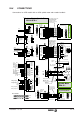
IN.9 ELECTRICAL CABINET DRAWINGS
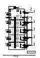
Let us first see which is the system power-up procedure.
The internal control circuits of each Power supply module, Drive or compact drive must be
supplied with 24Vdc.
Compact modules, XPS power supplies and the PS-25B power supply do not need an
external 24 Vdc power supply. These modules need two-phase 380-460 Vac.
Each module verifies its hardware and internal configuration.
If the status is correct, the DRO.OK contacts are closed.
If all the drives are OK, the Power Supply closes its "System OK" contact.
We supply mains power to the Power Supply module.
The Power Supply "loads" the Power Bus with a "Soft Start".
We activate the Drive_Enable control input of each Drive.
We activate the Speed_Enable control input of each Drive and the System_Speed_Enable
input of the Power Supply.
The motor is now ready to follow the velocity command given by the CNC.
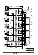
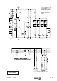
The following diagrams for power and control circuits in the electrical cabinet are only
orientative for the technician designing the machine and they may be further completed or
simplified at will according to each application.
Next, we offer a brief description of the function of each part of the circuit.
When turning the main switch on (Q1), the 24 V power supply powers the control circuit of
each module. These circuits perform an internal test of the module. If there is no errors, the
corresponding Driver_OK contact closes and this status is communicated to the Power
Supply module via the internal bus. If all the modules associated with a Power supply are "OK"
and the latter does not detect any errors in its own module, it closes the System_OK contact.
In the case of the compact modules as well as the XPS and PS-25B power supplies, the
closing of Q1 must take two phases to connector X1 without the need for external fuses.
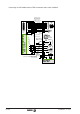
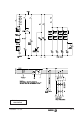
Emergency line. The D1 relay confirms that the system is mechanically and electrically in
working condition and it will be activated by the System_OK contact of the Power Supply. D1
will be deactivated if an emergency occurs at the CNC, if the operator presses the E-stop
button (mushroom), if the SPM motor overheats or if any axis of the machine hits the end-of-
travel (limit) switch. A normally open push-button is included in parallel with the limit switches
in order to be able to take apart the axes of the machine.
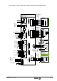
We are now ready to turn on the system by pushing the ON button which activates contactor
K1. By pushing OFF, power can be removed.
Error Reset. Should any module have errors, its Driver_OK and the System_OK would be
open, D1 deactivated, and the Power Supply could not be powered up. Some of these errors
may be eliminated by applying 24 Vdc to the Error_Reset pin of the Power Supply. The errors
are reset by means of the contact associated with the ON button. This may cause the
Driver_OK and System_OK contacts to close activating D1 and, while ON is pressed,
activate K1.