
Specifications
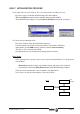


Common Setup Ver. 0002 GSU - 15
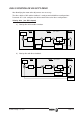
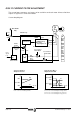
FeedbackResolver
RhoCorrection
RP5 -F1504-
To Speed Loop
VelocityFeedback
SV2 -S40-
Feedback
SineGain
RP3 -F1502-
RP1 -F1500-
RP4 -F1503-
RP2 -F1501-
RV1 -F1506-
RV2 -F1507-
X4 (DDS)
Feedback
CosineGain
Feedback
SineOffset
Feedback
CosineOffset
HV2-X3 Board Id
Rotor Sensor
From Motor
Sensor
0: Sine-wave Encoder r
1: Resolver
2: Square-wave Encoder r
GP2=2
GP2=1
GP2=0
Sensor
Evaluation
GP2 -F701-
Encoder
RV3 -F1508-
Feedback
RhoCorrection
Sensor
Position
Position
Speed
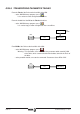
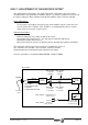
GSU.11 ADJUSTMENT OF THE ENCODER OFFSET
After adjusting the control loops, the motor might make a high-pitch noise due to some
misadjustment in the generation of feedback signals. To solve this problem, the offsets and
the gains used by the drive software to handle the feedback signals must be adjusted.
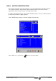
Circle adjustment.
It is the process that adjusts the processing of the feedback signals so the Sine and
Cosine signals (RV1 -F01506-, RV2 -F01507-) are mathematically correct. In other
words, they have to make a perfect circle.
Adjustment procedure:
- Make the motor turn very slowly, at about 5 to 10 rpm.
- Set variable RV8 -F01519- to "1". This will start the automatic adjustment.
- Monitor this variable RV8 -F01519- .
- When RV8 -F01519- recovers its default value (0), the adjustment will be concluded.
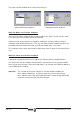
This procedure, which may last up to 2 minutes, modifies the values of
RP1 -F01500-, RP2 -F01501-, RP3 -F01502- and RP4 -F01503-,
eliminating the noise and improving the control over the motor.
Once this procedure is completed, Save to Flash and do a Reset .