
Specifications

SSU - 8 Velocity Drive Setup Ver. 0002
SSU.5.2 SPEED-PI ADJUSTMENT
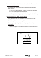
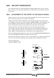
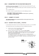
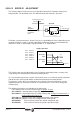
The Velocity Loop basically consists of a Proportional-Integral (PI) controller shown in the
diagram below. The operation of this PI is determined by two constants:
Kp
and
Ti
.
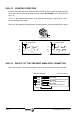
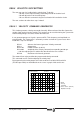
For better system performance,
Kp
and
Ti
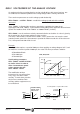
may be assigned different values depending on the
speed of the motor. Usually, a greater proportional and integral factor is preferred when the
motor turns slowly. In other words, high
Kp
and low
Ti,
as shown below:
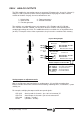
The Velocity Loop may be adjusted by using an internal command (previous section) or by
using directly the command of the external controlling device.
It is very common to generate a square signal which serves as an internal velocity command
and observe the actual speed and the command itself through the analog outputs.
To make the system adjust its performance to a particular external command, it must be
applied between pins 4 and 5 of connector X7, (or between pins 2 and 3 of X7 through the
auxiliary input).
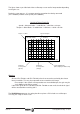
The following parameters are available for the adjustment:
is the integral factor (Ti) of the Velocity Loop. A greater Ti factor
SP1 -S00100- is the proportional factor (Kp) of the Velocity Loop.
SP2 -S00101- is the integral factor (Ti) of the Velocity Loop. A higher
Ti
factor means a
smaller integral effect of the PI.
SP4 -S00111- adapts the value of the proportional action at low speeds.
SP5 -S00112- adapts the value of the integral action at low speeds.
SP6 -S00209- is the maximum limit for the speeds considered "low".
SP7 -S00210- is the minimum limit for the speeds considered "high".
Speed
Gain
SP4*SP1
SP1
SP7
SP2
SP5*SP2
SP6
Kp
Ti
Adapter-Speed-PI:
SP1 -S00100-
SP2 -S00101-
SP4 -S00211-
SP5 -S00212-
SP6 -S00209-
SP7 -S00210-
Velocity
Command
Final
Velocity
Feedback
SV2
-S00040-
SV7
-F01612-
K
P
T
i
+
+
1
From Rotor Sensor
+
-
Speed-PI
To
Current Loop