
Specifications

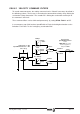

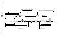

SSU - 10 Velocity Drive Setup Ver. 0002
DS1
Voltage/Current
Dip-Switch
WV1, WV2, WV3,
WV4, WV5.
WV4=0
WV4=1
SERCOS
Interface
In
Out
X7(3)
X7(2)
Id
IP1=2
IP1=1
SP31
WV5
IV1
IV2
SP30
Id=0
SP20
SP21
ratio
P2
P1
SV1
Analog Input 2
Analog Input 1
X7(5)
X7(4)
Id<>0
SP10
SV7
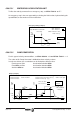
SpeedEnable Function
Ramps
ErrorStop
OR
SpeedEnable Function
me an s
PWM_OFF
if the motor
has not stopped in a
time period
GP3
Halt Function
Error Stop
SP80<>0
SP80=0
SP70=0
SP70=1
Jerk
Acc. Emerg.
SV8
OR
OR
SP100=0
SP100=1
SP60...
...SP64
SP60
SP80
SP65
Command Management
Velocity
Loop
Current
Loop
From Rotor Sensor
Speed-PI
SV2
SV7
SP1, SP2,
SP4, SP5,
SP6, SP7.
Current
LP-Filter
CP30
CP31