
Specifications


Applications Ver. 0002 AP - 11
AP.1.3 CONTROL SIGNALS PLC8050/55 - DRIVE
Signals from the PLC 50/55 to the Drive.
The Drive "Speed Enable" and "Drive Enable" can now be controlled from the PLC 50/55
through the Sercos ring. To do that, the PLC 50/55 now offers two new output logic variables:
SPENAn (SPeed ENAble n) (n=1..7) (M5110, M5160, M5210, M5260, M5310, M5360 and M5410)
SPENAm (SPeed ENAble m) (m=S,S2,AS) (M5462, M5487and M5449)
Function: Identifies the electrical signal "Speed Enable" of connector X2 of the Drive.
Possible values: 0 Disables the velocity command. Motor with command zero.
1 Enables the velocity command. The motor follows the command.
DRENAn (DRive ENAble n) (n=1..7) (M5111, M5161, M5211, M5261, M5311, M5361 and M5411)
DRENAm (DRive ENAble m) (m=S,S2,AS) (M5463, M5488 and M5448)
Function: Identifies the electrical signal "Drive Enable" of connector X2 of the Drive.
Possible values: 0 Disables the Drive. The motor has no torque.
1 Enables the Drive.
The "Speed Enable" function at the drive will be activated when the SPENA variable is
activated and the electrical signal Speed_Enable is activated at the pins of connector X2.
The "Drive Enable" function will be activated when the DRENA variable is activated and the
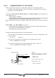
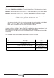
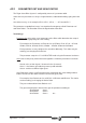
electrical signal Drive_Enable is activated at the pins of connector X2. See diagram below.
Safety regulations (EN-60204-1) demand the Drive Module to have an input
non-software related to guarantee that the motor will stop.
The hardware control over the electrical signal "Drive_Enable" MUST
NOT be removed even when using the Sercos interface.
OR
Halt Function
BV1 -F201-
BV3 -F202-
DV32 -S134-
(bit 13)
OR
DriveEnable
Function
(X2)
BV7 -F203-
DV32 -S134-
(bit 14)
DriveEnablePin
DriveEnableDnc
DriveEnable (Sercos)
-DRENA-
HaltDrivePin
HaltDriveDnc
Halt (Sercos)
OR
(X2)
DV32 -S134-
(bit 15)
SpeedEnablePin
SpeedEnable (Sercos)
-SPENA-
SpeedEnable
Function