
Specifications


AP - 12 Applications Ver. 0002
Signals from the Drive to the PLC 50/55.
The Drive offers two bits to the PLC 50/55 to indicate the operating status.
These are: DRSTAFn and DRSTASn. The table below shows the meaning of these signals.
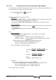
DRSTAFn (DRive STAtus First n) (n=1..7,S,S2,AS) (M5603, M5653, M5703, M5753, M5803, M5853
and M5903 at the axes. M5953, M5978 and M5557 at the spindles)
DRSTASn (DRive STAtus Second n) (n=1..7,S,S2,AS) (M5604, M5654, M5704, M5754, M5804,
M5854 and M5904 at the axes. M5954, M5979 and M5556 at the spindles)
Function: They are the bits indicating the Drive status to the PLC. This way, the PLC program
will handle the drive control signals depending on its status.
Possible values: 0,1 with the meaning explained in the next table.
Important:
As a general rule, the PLC assigns the id numbers to all the axis variables in the following
order: X, Y, Z, U, V, W, A, B and C. The SERCOS id numbers (SERCOSID,
Node_Select) assigned to the drives have nothing to do with this.
If the machine has three axes (for example: X,Y,B):
Variables SPENA1, DRENA1, and bits DRSTAF1 and DRSTAS1 will correspond to the X axis,
those with the index 2 to the Y axis and those of the index 3 to the B axis.
Those with the S, S1 and AS index will correspond to the main, second and auxiliary spindle
respectively.
The installation manual of the 8050/55 also mentions these PLC variables.
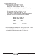
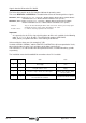
DRSTAFn DRSTASn
Status Action
00
The Drive is not ready. Do not apply Mains power to the
Power Supply.
Check the 24 Vdc, and/or solve the
errors.
01
The Drive is ready to receive Power at the Bus. The
Drive_OK contact is closed.
Apply Mains power to the Power
Supply.
1 0 The Drive is ready to attend to the control signals.
Enable the Drive with Drive_Enable
and Speed_Enable.
11
The Drive_Enable and Speed_Enable functions activated.
The motor follows the command.
Govern the motor with the command.