
Specifications

Design Ver. 0002 DS - 11
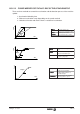
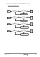
DS.2.2 CALCULATION OF ACCELERATION AND BRAKING TIME
After selecting the mechanical characteristics and the power of the Drive, the acceleration and
braking time is calculated as follows.
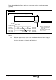
Constant torque area (0 < N
M
< N
B
):
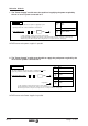
Constant power area (N
B
< N
M
< N
Max
) :
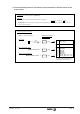
Constant torque and constant
power area (0 < N
M
< N
Max
) :
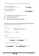
where:
J
M
is the inertia of the load in kg.m
2
as viewed from the motor shaft.
T
M
is the rated torque in KW at the base speed.
N
MAX
is the maximum motor speed in rpm.
N
B
is the base motor speed in rpm.
N
M
is the motor speed in rpm after the acceleration time.
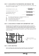
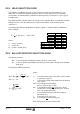
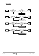
DS.2.3 CALCULATION OF POWER WITH INTERMITTENT LOAD
Forming the Drive to the right dimensions has to be done with the greatest care when the
application involves a periodical starting and stopping operation, frequently repeated as in the
case of threading with a miller. For a cycle like the one shown in the figure, which includes
acceleration and stopping, the equivalent effective torque T
R
of Equation 16 must be within the
S1 dimension given for the Drive torque. The maximum T
P
value is 120% of dimension S2 30
minutes of the Motor.
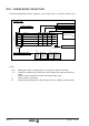
DS.2.4 DRIVE SELECTION
Once the motor has been selected, check the characteristics curves in the AM chapter.
These curves indicate the power that the various drives can obtain from that motor.
ttt
JN N
TN
MM B
MB
312
22
2
120
=+=
+
π
*( )
**
(seg.)
T
Ttt Tt
t
R
Prf Ls
c
=
++
22
*( ) *
(Nm)
t
JN
T
MM
M
1
2
60
=
π
**
*
(seg.)
t
JN N
TN
MM B
MB
2
22
2
120
=
−
π
*( )
**
(seg.)
Time
Tp
Ti
Tc
Speed Torque
-Tp
Nm
Tr
Ts Tf
Time