
Specifications


A - 10 Parameters, Variables and Commands Ver. 0002
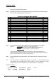
1. GROUP APPLICATION “A”.
Function: It determines the way it operates as far as the system configuration is concerned.
Bit Name
————————————————————————————-
4
3 It sets the activation of Feedforward ( when working with
position command)
= 1 Feedforward active
= 0 Feedforward cancelled
2 It determines whether the motor feedback or direct feedback
is used.
= 1 Direct X feedback
= 0 Motor feedback
1, 0 (LSB) Determine whether it is a velocity or position command.
= 10 Velocity command (without position loop)
= 11 Position command
See the section on "Velocity or Position Drive" in the GSU chapter of this manual.
Valid values: 1..15 (3 by default, position loop with motor feedback).
AP5 O (F2001) PlcPrgScanTime
Function: It determines the repetition period of the main PLC module (PRG)
Valid values: 4, 8, 12, 16 or 20 ms (4 ms, by default)
2. NON-PROGRAMMABLE INPUT-OUTPUT "B"
Groups the variables related to the non-programmable hardware control signals and logic variables
associated with the Halt and Drive_Enable functions through the serial line.
Activating the Halt function means setting the velocity command to zero while keeping the rotor locked (with
torque). It can be activated by means of an electrical signal at certain digital inputs of the drive using the
monitoring program through the serial line or Sercos interface.
The Halt function is activated (stops the motor) when applying zero volts to the electrical input assigned to
variable BV1, when requested from the monitoring program (variable BV3=0), or when requested from the PLC
of the CNC via Sercos (bit 13 of DV32 set to 0).
BV1 O (F201) HaltDrivePin
Function: Controls the Halt function through an electrical signal. BV1 is assigned to the
parameter IP10-IP13 corresponding to the digital input that will be used as Halt.
Default value: 1 (it has no effect).
Example: IP11 = BV1 (digital input 2 performs the Halt function. In other words, applying 0V to
pin 2 with respect to pin 5, activates the Halt function and the motor stops).
Version: Available from version 02.01 on.
BV3 O (F202) HaltDriveDnc
Function: Controls the Halt function through the serial line.
Default value: 1 (it has no effect).
Example: BV3 = 0 (activates the Halt function).
Activating the DriveEnable function enables the current to flow through the Motor.
It can be deactivated by means of an electrical signal at the control connector X2 of the Drive, from the
monitoring program through the serial line or via Sercos interface.
The DriveEnable function is deactivated (removes motor torque) when applying zero volts at that electrical
input, when requested from the monitoring program (variable BV7 = 0), or when requested from the PLC of the
CNC via Sercos (bit 14 of DV32 -variable DRENA at the PLC- is set to 0).