
Specifications


Electronic Modules Ver. 0002 EM - 33
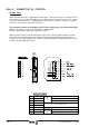
Deactivation of the Drive Enable input
The “Drive Enable” input (pin 2) controls the Current Loop by hardware.
When it is powered with 24 Vdc, the Current Loop is enabled and the drive can work.
If the "Drive Enable" input is set to 0 Vdc, the power circuit turns off and the motor loses its
torque. In this situation the motor is no longer governed and will turn freely “stopping by
friction”.
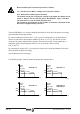
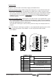
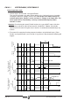
Deactivation of the "Speed Enable" function
When Speed_Enable is set to 0 Vdc, the "internal velocity command" switches to 0 rpm and:
Case 1: The Torque is kept active by braking the motor. When it stops, variable
SV5 -S00331- is activated. The motor has stopped in a time period shorter than the
one indicated by parameter GP3 -F00702-. The torque is canceled and the rotor is
free.
Case 2: The Torque is kept active by braking the motor. The motor does not stop in a time
period shorter than the one indicated by parameter GP3 -F00702-. Error-4 is issued,
the torque is canceled and the rotor is free. The motor stops when its inertia runs out
(by friction).
GP3 and SV5 -S00331- are internal parameters and may be consulted in Appendix A.
Safety standards (EN-60204-1) require the drive module to have a software
independent input in order to always assure that the motor will stop.
The "Drive Enable" input, using only hardware, can cancel the Power
Circuit leaving it deactivated.. This allows stopping even when the
software fails.
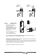
In case of mains failure, the control circuit and its signals
must maintain
their 24 Vdc while the motors are braking.
On the Modular Drive, the 24 Vdc for supply and "Drive_Enable" activation
must be provided by a power supply that can maintain it during that time.
The Power Supply PS-25B, the Auxiliary Power Supply APS 24 and the
Regenerative Power Supplies XPS meet this condition.
In the case of the Compact Drive, the 24 Vdc at pins 1 and 2 meets this
requirement and are appropriate for managing the control signals.