
Specifications


EM - 38 Electronic Modules Ver. 0002
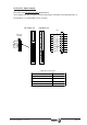
EM.4.7 CONNECTORS AT SL1 AND SL2
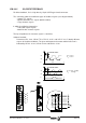
EM.4.7.1 A1 card
The A1 card must always be in SL1.
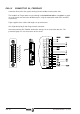
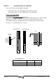
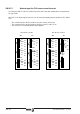
X6, digital inputs and outputs
It offers four digital inputs and four digital outputs, all of them fully programmable.
The digital inputs are optocoupled and referred to a common point (pin 5).
The digital outputs are contact type and also optocoupled.
Each input and output is associated with a parameter as shown in the diagram.
The operator may assign internal boolean type variables to these parameters (for example:
SV3 -S00332-, SV5 -S00331-, TV10 -S00333-, etc.) in order to indicate the system status
through electrical contacts. These variables are set by means of the monitoring program for
PC or through the DDS PROG MODULE.
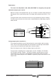
Digital Inputs Characteristics:
Nominal voltage (maximum) 24 Vdc (36 Vdc)
Turn-on/off Input voltage 18 Vdc / 5 Vdc
Typical consumption (maximum) 5 mA (7 mA)
Digital Outputs Characteristics:
Maximum voltage 250 Volts
Maximum load current (peak) 150 mA (500 mA)
Maximum internal resistance 24 Ohms
Galvanic isolation voltage 3750 Volts (1 min)
(OP13 -F01407-)
(OP12 -F01406-)
(OP11 -F01405-)
(OP10 -F01404-)
IN 4
IN 3
IN 2
(IP13 -F00904-)
(IP12 -F00903-)
(IP11 -F00902-)
(IP10 -F00901-)
OUT 4
OUT 3
OUT 2
OUT 1
REF-IN
IN 1
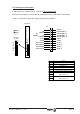
1
13
7
6
3
5
4
8
2
1
9
11
13
12
10
Pin
(Phoenix,
3.5 mm)
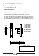
X6-DIGITAL I/Os
A1
1
1
X7-ANALOG I/Os X6-DIGITAL I/Os
P2P1
(A1 Board)