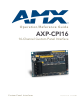
Operation/Reference Guide AXP-CPI16 16-Channel Custom Panel Interface Cu st o m P a n e l I n t er f a c e s L as t R e vi s ed: 1 /1 3 /20 0 9
AMX Limited Warranty and Disclaimer AMX warrants its products to be free of defects in material and workmanship under normal use for three (3) years from the date of purchase from AMX, with the following exceptions: • Electroluminescent and LCD Control Panels are warranted for three (3) years, except for the display and touch overlay components that are warranted for a period of one (1) year.
Table of Contents Table of Contents Product Information ...........................................................................................1 Specifications............................................................................................................ 1 Installation ..........................................................................................................3 Mounting Dimensions ...............................................................................................
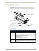
Product Information Product Information The AMX AXP-CPI16 16 Channel Custom Panel Interface Board (FIG. 1) simplifies the process of creating custom control panels for Axcess systems. Providing contact closure inputs and feedback outputs for up to 16 buttons, the miniature PC board contains a 20-pin header for ribbon cable installation or for direct mounting to a printed circuit board.
AXP-CPI16 Specifications (Cont.) AXlink Status LED Indicates AXlink communication status as follows: • One blink per second communication is functioning. • Two blinks per second devices specified in the master program do not match the specified devices found. • Three blinks per second indicate an AXlink communication error. • Full-on indicates there is no AXlink control or activity (but power is on), or the Axcess program is not loaded. 2 Device DIP Switch 8-position DIP switch sets AXlink device ID.
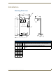
Installation Mounting Dimensions LH B B AA A A C C AXlink AXlink GND PWRAXP AXP AXM GND L J P1 1 1 22 P1 PWR AXM P3 P3 Top View (Component Side) Top View (Component Side) DD E E P2 P2 2 11 19 19 20 20 MM 20 20 19 19 J G F F KG H K min min FIG. 1 AXP-CPI16 mounting dimensions Mounting Dimensions Item Inch mm Item Description A 0.10 2.50 K B 1.75 44.50 L 0.125 Inch (3.2 mm) mounting holes for #4-40 (3 mm) screws C 1.55 39.40 M P3 20-Pin Header .
Setting the AXlink Device Number The 8-position device DIP switch defines the AXP-CPI16 as an AXlink device. It can be one of 255 devices in the Axcess Control System. Set the device number with the total value of all ON (down) positions. As an example, the device DIP switch shown below defines device number 129 (1+128=129). Position 1 2 3 4 5 Value 6 7 8 OFF OFF 1 2 4 8 16 32 64 128 ON ON 1 2 3 4 5 6 7 8 AMX standard device numbers are assigned as follows: Cards are 1 through 25.
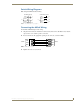
Switch Wiring Diagrams FIG. 2 diagrams LED and Switch wiring. LED Wiring (Typical) 10 LED 1 1K LED 2 1K LED 3 1K Switch Wiring (Typical) SW 1 1 2 12 3 SW 2 SW 3 13 14 15 FIG. 2 LED and switch wiring diagrams Connecting the AXlink Wiring To install the AXlink data/power bus wiring. 1. Strip 0.25 inch off the wire insulation for all four wires. If the wire is 20 AWG or less, fold the exposed wire over to obtain a positive connection. 2.
Programming Programming Use the same Axcess commands as with other AXlink control panels, such as the AXU-MSP series mini-softwire panels. When using the AXP-CPI16 as a control device, use On, Off, and Pulse commands to control sources connected to outputs and Push and Release commands to receive inputs. For additional information, refer to the Axcess Programming Language instruction manual. Send_Commands Command Description Causes the AXP-CPI16 to be in Status-On Mode.
Testing the Unit If you have programmed the Axcess software, load the program into a PC connected to the control system Master port. See Programming on page 4. 1. Push switches connected to the AXP-CPI16. 2. Look at the lower left of the Axcess screen to verify that the correct device and channel numbers are displayed. 3. Check for the appropriate feedback (as provided by the Master Controller program).
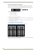
AXP-CPI16 System Worksheet AXP-CPI16 System Worksheet Dealer ID Date Dealer PO Number Job SO Number Description Serial Number Rev Number Device Number HEADER P2 Channel 1 2 3 20-PIN HEADER 1 13 2 14 3 15 4 4 16 5 5 17 6 6 7 18 7 19 8 8 20 In In Out Out In In Out Out In In Out Out In In Out Out In In Out Out In In Out Out In In Out Out In In 9 N/C N/C 11 N/C N/C 10 +12 +12VDC PWR VDC PWR 12 PinNumber Number Pin FUNCTION Out Out GND GND AXP-CPI16 16-Channel Custom Panel
HEADER P3 Channel 9 10 11 1 13 2 14 3 15 4 12 16 13 17 5 6 14 15 18 7 19 8 16 20 20-PIN HEADER FUNCTION Out Out In In Out Out In In Out Out In In Out Out In In Out Out In In Out Out In In Out Out In In Out Out In In 9 N/C N/C 11 N/C N/C 10 +12 VDC PWR +12VDC PWR 12 GND GND Pin Number Pin Number 10 AXP-CPI16 16-Channel Custom Panel Interface
1/09 ©2009 AMX. All rights reserved. AMX and the AMX logo are registered trademarks of AMX. AMX reserves the right to alter specifications without notice at any time. It’s Your World - Take Control™ 3000 RESEARCH DRIVE, RICHARDSON, TX 75082 USA • 800.222.0193 • 469.624.8000 • 469-624-7153 fax • 800.932.6993 technical support • www.amx.