
Specifications

SLAA154
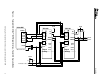
8 Interfacing the TLV320AIC12/13/14/15 Codec to the TMS320C5402™ DSP
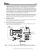
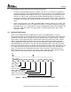
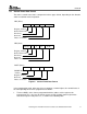
Within each frame, the data frame for each device is transmitted first in one block, immediately
followed by the corresponding control frame block. This process is repeated indefinitely, until the
data frame select bit, bit D6 of CR1 is set, implying a continuous data transfer request.
Subsequently, the serial shift clock rate is automatically halved, and the control frame block is
dropped—see Figure 4.
FS
DIN / DOUT
Master Data
Slave Data
Master Data (next frame)
Slave Data (next frame)
Figure 4. Master / Slave Communication in Continuous Mode
Note that in both cases the frame synchronization rate is not changed; only the shift clock rate
(not depicted) is changed. In this mode, the data frame of the DIN terminal carries 16-bit data
from the DSP to the codec’s DCA data register, while the data frame of the DOUT terminal
carries the numerical results of the codec’s ADC to the DSP.
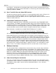
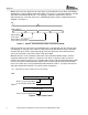
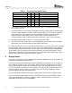
While the device is in the continuous data mode, if the LSB of the DIN bit string is clear the
continuous data transfer continues. If, however, the LSB is set, then the codec assumes a
control frame request has been issued, and the codec reverts to the programming mode of data
transfer, one block of data followed by another block of control data for each synchronization
frame. The codec stays in this programming mode until bit 6 of CR1 is set. Figure 5 shows the
data frame format for the AIC12 in its various modes of operation.
(15 + 1) Bit Mode (Continuous Data Transfer Mode Only)
DIN
DAC Converter Input Data
Control Frame Request Bit
DOUT
A/D Converter Output Data
Figure 5. Data Frame Format
D15 through D1 D0
D15 through D0