instruction manual 6" Color Video Touch Panels (Firmware version G3) Touc h Pa n els an d A cc e ss o r ie s
AMX Limited Warranty and Disclaimer AMX Corporation warrants its products to be free of defects in material and workmanship under normal use for three (3) years from the date of purchase from AMX Corporation, with the following exceptions: • Electroluminescent and LCD Control Panels are warranted for three (3) years, except for the display and touch overlay components that are warranted for a period of one (1) year.
Table of Contents Table of Contents Product Information .................................................................................................1 Specifications .................................................................................................................... 1 Cleaning the Touch Overlay.............................................................................................. 4 Installation .....................................................................................
Table of Contents Using TPDesign3 to Download Bitmaps, Icons, and Fonts............................................. 27 Creating a Bargraph and Joystick ................................................................................... 27 Adding a bargraph or joystick button\..................................................................................... 28 Setting Bargraph and Joystick Properties ....................................................................... 28 Setting the level code......
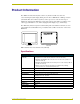
Product Information Product Information The AMX Color Video Panels (CV6) contain a 6" (14.40 cm visible area) 256-color active-matrix liquid crystal display (LCD) placed in either a Wall Mount or Tabletop enclosure (AC-CV6T). This self-contained system uses a microprocessor to control a wide range of multimedia equipment. The TPDesign3 touch panel design program makes it possible to create custom pages with buttons, icons, sliders, bargraphs, time displays, logos, and drawings.
Product Information Specifications AXD-CV6 (Cont.) Memory: • 512 KB of SRAM and 2 MB of Flash for a total memory of 2.5 MB.
Product Information Specifications AXD-CV6 (Cont.) Rear Connectors: AXlink 4-pin bus connector for connection to the AMX Central Controller. PWR +12 VDC power supply; power is supplied through the bus or an external PSN power supply. RS-232 DB-9 male connector for data transmission or Microsoft® mouse control Video BNC female connector (NTSC/PAL/SECAM) Character Support: Unicode® character support for far-eastern languages such as Chinese.
Product Information Finishing Instructions for Aluminum AC-CV6T (FG5924-22). Surface preparation for the Aluminum CV6T is very important. The unfinished aluminum version of the AC-CV6T is supplied with a sanded, non-coated aluminum bezel, aluminum panel mounting blocks, and a stainless steel base enclosure. Please consult a qualified painter for the appropriate surface treatment compatible with the end users desired topcoat.
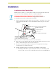
Installation Installation Installation of the Conduit Box Wall Mount panels (AXDs) are contained within a metallic outer housing (back box). This back box is not removed when installing the AXD into a conduit box (CB-CV6). INSTALLER: LEAVE A GAP BETWEEN THE STUD AND CONDUIT BOX TO ACCOMMODATE THE DRYWALL SHEETROCK. This gap allows the installation of the drywall/sheetrock after the conduit box has been installed. 1. Fasten the CB-CV6 to the stud through the tabs shown in FIG. 3.
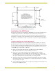
Installation .308 7.8MM 6.174 156.8MM .309 7.8MM .144 3.7MM NOTICE: THIS CUTOUT IS INTENDED FOR MOUNTING THE CB-CV6 CONDUIT WALLBOX ONLY. IF INSTALLING AXD-CV6 WITHOUT CONDUIT WALLBOX USE THE MOUNTING TEMPLATE SUPPLIED WITH AXD-CV6, OR REFER TO AMX MOUNTING SPECIFICATION SP9524-01 2.900 73.7MM 4.624 117.5MM AXD-CV6 BEZEL OUTLINE .862 21.9MM .018 0.5MM 6.210 157.7MM .606 15.4MM RECOMMENDED CUTOUT CUTOUT SHOWN FOR CONDUIT WALLBOX WITH TABS REMOVED FIG.
Installation Removable tabs used to mount the box to a stud beam C - Optional CB-CV6 conduit/wallbox Install the (2) #4-40 screws into the places indicated Cable knockouts Installed flush against a solid surface Do not use these Mounting tabs to mount the conduit /wallbox A - Decor faceplate B - Main AXD unit consists of the touch panel and backbox housing FIG.
Installation Installing the AXD into a flat or solid surface To install AXD-CV6 touch panels: 1. Remove the magnetically attached Decor faceplate (A in FIG. 6) from the main AXD unit (B in FIG. 6) by gripping the faceplate and pulling with gentle force. Solid surface (can include a wall, podium, or other level surface) Install the #4-40 machine screws into the holes shown below. These 4 screws are removed to access or replace the battery. Screw length depends on the installation surface.
Installation 6.79 (BEZEL) 6.21 .12 5.97 .28 REF .76 ZERO RADIUS REQUIRED IN THESE 4 CORNERS. THESE 4 HOLES ARE ONLY REQUIRED WHEN MOUNTING UNIT TO A SOLID SURFACE (PODIUM, DESK, ETC.). SECURE UNIT WITH #4 SCREWS. SUGGEST INSTALLATION OF #4-40 THREADED INSERTS AT THESE 4 LOCATIONS. 2.900 4.43 5.37 (BEZEL) CUTOUT FRONT BEZEL #4-40 machine screw inserts (#4 screws) used for mounting to a flat surface (provided by installer) FRONT BEZEL FIG.
Installation Surface mount screws are inserted through the outer holes along the housing. Four drilled holes correspond to the four (#4) screws used to secure the housing to the flat surface. FIG. 9 Screw locations for flat surface mounting of the main AXD unit Installing the AXD panel using Expansion clips (dry wall) Expansion clips are mounted through the two oval holes located at the sides of the panel. As the screw is tightened, the clip bends toward the insertion hole and into the wall.
Installation Flat surface (can include a wall, podium, or other level surface) Install the 2 drywall clips and screws (included) into the holes 2 notches are required if the unit is installed in drywall using the (2) provided clips A - Decor faceplate B - Main AXD unit consists of the touch panel and housing FIG.
Installation 5. Attach the data and power wiring to the touch panel. 6. Test the connection by reconnecting the AXlink connector to the Central Controller. Verify that the panel is receiving power and functioning properly to prevent repetition of the installation. 7. Disconnect the AXlink connector from the Central Controller until installation is complete. 8. Connect the data and power wiring to the rear of the touch panel. 9.
Installation Setup of the AC-CV6T Tabletop Enclosure The following paragraphs describe the setup procedures for installing the Wall Mount touch panel into a tabletop enclosure. The enclosure works by encasing an existing AXD-CV6 touch panel and using a tabletop cable (AXlink/Video) to connect the unit to both a Master Controller and video sources. Finishing Instructions for Aluminum AC-CV6T (FG5924-22). Surface preparation for the Aluminum CV6T is very important.
Installation Rear view Circular front of strain relief lies flush against enclosure Heat shrink CLIP FACING UP Strain relief is mounted on the edge of the heat shrink FIG. 14 Installation of relief/cable combo into the AC-CV6T enclosure VERIFY THE DIRECTION AND LOCATION OF THE STRAIN RELIEF. The clip must be facing UP (on top). Once closed, it is difficult to re-open. Grooves align against heat shrink and the flat circular opening faces away from the enclosure. Refer to FIG. 15 for more information. 5.
Installation 7. Firmly insert the cable/strain relief combo into the base enclosure opening by pushing the combo through the base opening (toward the inside) until the relief is securely flush against the base. Refer to FIG. 14 on page 14 for the final position of the strain relief/cable combo. 8. Position the base enclosure onto a flat surface. 9. Grip the CV6 unit, from either sides of the enclosure, and while angling the front of the CV6 unit upwards, connect the AXlink and BNC connectors (FIG.
Installation 11. Position the faceplate/bezel (D in FIG. 17) above the enclosure base. 12. Securely grab the LCD and enclosure unit combo (enclosure unit is made up of the base and faceplate). 13. Carefully flip the combo over onto a soft cloth to prevent scratching the faceplate during the installation of the mounting blocks. 14. Insert the mounting blocks (B in FIG. 17) into the opening below both sides of the faceplate. The elevated groove on the blocks should lie against the base enclosure. 15.
Installation Do not connect power to the touch panel until wiring is complete. If you are using a 12 VDC power supply, apply power to the touch panel only after installation is complete. Wiring guidelines The touch panel requires 12 VDC power to operate properly. The touch panel can use either a PS(N)2.8 (if the power is being supplied only to the touch panel) or a PSN6.5 power supply (if the power is being routed through the touch panel to power another device).
Installation Using the 4-pin AXlink for data with external power supply To use the AXlink 4-pin Phoenix connector for data communication (with the Central Controller) and power transfer (from a power supply), the incoming PWR and GND cable from the power supply must be connected to the AXlink cable connector going to the touch panel. FIG. 19 shows the external power supply diagram.
Installation Using a BNC video cable to provide video input Connect the control system’s video connector to the rear of the AXD-CV6 using a BNC cable to provide a video feed, as seen in FIG. 20. GND (-) Video wire BNC (female) connector Rear panel view AXD-CV6 BNC (male) connectors Female video source connector FIG. 20 BNC cable connection from the AXD-CV6 to the video source Some installations may require a 90° right-angle BNC adapter to accommodate a sharp bend in the video cable.
Installation Power connector + (PWR) - (GND) 12 VDC power supply Optional 7 to 8-pin connector 5 (GND) 5 (GND) 3 (TXD) 2 (RXD) 3 (TXD) 2 (RXD) Touch panel DB-9 connector Mouse or PC, DB-9 connector Male Female FIG.
Designing Touch Panel Pages Designing Touch Panel Pages There are two ways to approach creating touch panel pages: TPDesign3 - Refer to the TPDesign3 Touch Panel Program (Version 3. 16) instruction manual for more information. On-board editor This document describes basic use of the on-board editor to create pages and buttons. Refer to the G3 Firmware Design and Reference instruction manual for more detailed firmware information.
Designing Touch Panel Pages General Button Categories (Cont.) Status buttons Status buttons always have a dark fill with light letters and have no functionality except to display information. Operation bars Operation bars appear in the place of the Editor bar, after selecting a button or page edit operation. The operation bar indicates which edit function is currently active. When an edit operation is selected, it remains active until you press EXIT.
Designing Touch Panel Pages FIG. 23 Setup page 4. Press EDITOR to enable Edit mode. The EDITOR button is highlighted in the Protected Setup page when enabled, as shown in FIG. 24. FIG. 24 Protected Setup page with the active EDITOR button 5. Press EXIT to close the Protected Setup page and return to the Setup page (now the Edit mode). 6. Press EXIT again to return to the Main page. The EDIT button appears at the top of the page indicating Edit mode is active. 7. Press EDIT to open the Edit bar.
Designing Touch Panel Pages Setting the Device Base Press the DEVICE BASE option, in the Protected Setup page (FIG. 24), to assign a base (starting) device address to the touch panel. 1. Enter the base address for the touch panel. The base address range is from 1 - 255. Standard device addresses begin at 128. 2. Press ENTER to save. Setting the Device Used Use the DEVICE USED option in the Protected Setup page (FIG. 24) to assign a value for the number of devices being controlled by the touch panel. 1.
Designing Touch Panel Pages Defining On-Screen and External Button Properties External pushbuttons are configured with features similar to on-screen buttons. Their functionality can be set just as any other button on the touch panel. Use the PROPERTIES option of the BUTTON menu in the Edit bar to set button borders, page flips, button colors for channel on/off conditions, channel/variable text codes, and string/macro assignments.
Designing Touch Panel Pages Setting the variable text code The variable text buttons set the device and button channel codes for the buttons. 1. Press DEV to open the keypad and set the device number. 2. Enter 1, 2, 3, or 4 in the keypad. The source code uses device codes 1 - 4 to identify the touch panel. 3. Press ENTER to save, close the keypad, and return to the Button Properties page. 4. Press CHAN to open a keypad and set the channel number. 5. Enter a channel value of 1 - 255 in the keypad.
Designing Touch Panel Pages 4. Go through each option and set as desired: TEXT OFF and TEXT ON sets the text for the button's Off and On state. ICON OFF and ICON ON sets the icon for the button's Off and On state. BITMAP OFF and BITMAP ON sets the bitmap for the button's Off and On state. MAKE ON SAME AS OFF sets the On and Off properties the same. You cannot create or edit buttons with Unicode fonts on the panel.
Designing Touch Panel Pages Adding a bargraph or joystick button\ Create a new button using the Add operation bar in the BUTTON menu. 1. Press BUTTON in the Edit bar to open the BUTTON menu. 2. Press PROPERTIES in the BUTTON menu to open the PROPERTIES operation bar. 3. Press any button to open the Button Properties page. 4. Press BUTTON TYPE to open the BUTTON TYPE menus. Choose a button type to open its Button Properties page.
Programming Programming You can program the touch panel, using the commands in this section, to perform a wide variety of operations using Axcess Send_Commands and variable text commands. Use the commands described in this section to program the touch panel. Serial Commands Serial Commands are used in the AxcessX Terminal Emulator mode. These commands are case insensitive. Serial Commands ?PAR Returns panel parameters to the PC terminal.
Programming Serial Commands (Cont.) ECHO ON Syntax: Turns On character echo. Example: "ECHO ON" ECHO ON The character echo is sent back to the computer. ECHO OFF Turns Off character echo. Syntax: "ECHO OFF" Example: ECHO OFF The character echo is not sent back to the computer. GET CAL Gets the calibration variables. Syntax: "GET CAL" Example: GET CAL Gets the calibration variables on the touch panel. HELLO Verifies that serial communication is working properly.
Programming Serial Commands (Cont.) SETUP Syntax: Puts the touch panel on the Setup Page. Example: "SETUP" SETUP Flips the touch panel to the Setup page. VER Restores the current version. Syntax: "VER" Example: VER Returns the current version of the main firmware. WORKING? Syntax: Verifies the com"WORKING?" munication Example: between the touch WORKING? panel and the Terminal Emulator. Response: $SC 1,"’CPAGE72-Main Page’" Responding touch panel turns its Main page the color white.
Programming System Send_Commands (Cont.) ADBEEP Syntax: Outputs a double "’ADBEEP’" beep even if the Example: double beep value SEND_COMMAND TP,"’ADBEEP’" is set to 0 in the Setup page. Double beeps the panel. AKEYB The keyboard string is set to null during power-up and stored until power-down. Opens the touch panel keyboard and initializes the text string entry.
Programming System Send_Commands (Cont.) BRIT Syntax: Adjusts brightness "’BRIT-’" of display. Variable: level = 1 - 8 (1 = minimum; 8 = maximum) Example: SEND_COMMAND TP,"’BRIT-8’" Sets to highest brightness level. CALIBRATE Syntax: Starts the touch panel calibration sequence. Example: "’CALIBRATE’" SEND_COMMAND TP,"’CALIBRATE’" Starts the calibration operation on the touch panel. CLOCK Sets the time and date.
Programming System Send_Commands (Cont.) MOUSE Syntax: Turns on serial mouse or other touch devices. Variables: "’MOUSE ’" mouse condition = 00: Mouse cursor Off 01: Microsoft® serial mouse/cursor On Example: SEND_COMMAND TP,"’MOUSE 01’" Turns on Microsoft® compatible serial mouse. Refer to the @MOU section on page 42 for the chart describing the BIT information and definitions. PAGE Syntax: Flips to a page with a specified page name.
Programming System Send_Commands (Cont.) RESET Syntax: Cycles power on the touch panel. Example: "RESET" RESET Cycles the power on the touch panel. Once the firmware is downloaded, send this command to recycle power to the panel. This command prevents the user from having to physically re-cycling power on the unit. SETUP Goes to the Setup page. Syntax: "’SETUP’" Example: SEND_COMMAND TP,"’SETUP’" Flips the touch panel to the Setup page. SLEEP Syntax: Forces the touch panel to screen saver mode.
Programming System Send_Commands (Cont.) TPAGEON Syntax: Activates page tracking.
Programming System Send_Commands (Cont.) ZAP! Clears all memory; erases buttons, pages, drawings, and symbols. Syntax: "’ZAP!’" Example: SEND_COMMAND TP,"’ZAP!’" Clears all memory and erases all buttons, pages, drawings, and symbols. Only use the ZAP! command to erase the saved data in the touch panel; data cannot be recovered after it is erased. Video Send_Commands Video Send_Commands direct the touch panel to perform various video specific operations.
Programming Video Send_Commands (Cont.) @VDD Sets the video setting for autodetection or manual detection of the video standard. Syntax: "’@VDD ’" Variables: ASCII detection settings = 1: Auto-detect video input 2: Manual set NTSC 3: Manual set PAL 4: Manual set SECAM Example: SEND_COMMAND TP,"’@VDD 3’" Detects only PAL. @VFF Video Fast Forward Mode Alogrithm.
Programming Programming Numbers The following information provides the programming numbers for colors, fonts, and borders. Colors can be used to set the colors on buttons, sliders, gauges, and pages. The lowest color number represents the lightest color-specific display; the highest number represents the darkest display. For example, 0 represents light red, and 5 is dark red. Colors and Programming Numbers Color No. Color No.
Programming Shorthand Send_Commands The shorthand commands operate control equipment just like standard Send_Commands still used in a wide variety of AMX products. However, shorthand commands are smaller byte-for-byte, and are processed more efficiently. The table below lists the shorthand Send_Commands you can use with the AXD-CV6 touch panel. The shorthand command data is 1-byte, non-ASCII format except for pages, passwords, text, and bitmap names.
Programming Shorthand Send_Commands (Cont.) @CPG This only works if the new background color is not the same as the current color. Sets the specified page’s background color to the specified color. Syntax: "’@CPG’,,’’" Variables: color number = See the Colors and Programming Numbers table on page 39. page name = 1 – 50 ASCII characters Example: SEND_COMMAND TP,"’@CPG’,87,’Main Page’" Sets the page title to Main Page, and the color to Black.
Programming Shorthand Send_Commands (Cont.) @IDP Queries the touch panel to return a string with the TPDesign3 project name. @MOU Sets the serial touch interface type. Syntax: "’@IDP’" Example: SEND_COMMAND TP,"’@IDP’" The touch panel returns a string containing the TPDesign3 project name. When changing the serial touch device, you must connect the hardware before setting the device type.
Programming Shorthand Send_Commands (Cont.) @PPN If a page name is empty the current page is used. Activates a popup page on a touch panel page. Syntax: "’@PPN-;’" Variables: popup page name = popup page name page name = page name Example: SEND_COMMAND TP,"’@PPN-Laser Disc 2 Transport Control; Laser Disc Control Page’" Activates the Laser Disc 2 Transport Control popup page on the Laser Disc Control Page.
Programming Shorthand Send_Commands (Cont.) @SWK Changes the Wakeup string sent to the Controller when the touch panel is activated. Syntax: "’@SWK-’" Variable: string = alphanumeric characters Example: SEND_COMMAND TP,"’@SWK-Touch Panel Activated’" Sends Touch Panel Activated to the Central Controller. Color Send_Commands Use the color Send_Commands to set the colors for text, buttons, and pages.
Programming Color Send_Commands (Cont.) CBOFF Syntax: Sets the OFF feedback border color to the specified color. Variables: "’CBOFF-’" variable text address = 1 - 255 color number = See the Colors and Programming Numbers table on page 39. Example: SEND_COMMAND TP,"’CBOFF1-72’" Sets the OFF feedback border color to White for the variable text button 1.
Programming Color Send_Commands (Cont.) CTOFF Syntax: Sets the OFF feedback text color to the specified color. Variables: "’CTOFF-’" variable text address = 1 - 255 color number = See the Colors and Programming Numbers table on page 39. Example: SEND_COMMAND TP,"’CTOFF1-87’" Sets the OFF feedback text color to Black for variable text button 1.
Programming Variable Text Send_Commands (Cont.) !C Sets the border, font, and text in one command. Syntax: "’!C’,,,,’’" Variables: variable text address = 1 - 255 border style = See the Border Styles and Programming Numbers table on page 39. font size = See the Font Styles and Programming Numbers table on page 39. new button text = Enter button text to appear on the button.
Programming Variable Text Send_Commands (Cont.) !T Syntax: Shorthand version of 'TEXT' command. Variables: "’!T’,,’’" variable text address = 1 - 255 new button text = 1 - 60 characters Example: SEND_COMMAND TP,"’!T’,1,’VCR PLAY’" Changes the title on variable text button one to VCR PLAY. TEXT Use the | character to display text on multiple lines. Enters text on a button.
Programming Shorthand Variable Text Commands (Cont.) @BMF This command allows you to program up to 12 attributes on one command line. Sets multiple Syntax: attributes to a but"’@BMF’,,’’" ton, slider, or Variables: gauge. variable text address = 1 - 255 attribute data: ’%R,, , , ’ = Sets the rectangle position. ’%B’, = See the Border Styles and Programming Numbers table on page 39.
Programming Shorthand Variable Text Commands (Cont.) @FON Syntax: Sets the text font on a button. Variables: "’@FON’,," variable text address = 1 - 255 font style = See the Font Styles and Programming Numbers table on page 39. Example: SEND_COMMAND TP,"'@FON',56,32" Sets the text on button 56 to variable font style 32. @ICO Assigns an icon to a button.
Programming Shorthand Variable Text Commands (Cont.) @TXT Use the | character to display text on multiple lines. Adds text to a but- Syntax: ton. "’@TXT’,,’’" Variables: variable text address = 1 - 255 text = Enter button text to appear on the button. Example: SEND_COMMAND TP,"’@TXT’,2,’VCR|PLAY’" Sets the VCR and PLAY text on variable button 2. The | character places VCR on a text line above PLAY on the button.
Programming Button String Commands (Cont.) $SC Sends a serial port send_command within a panel, as if sent from Axcess. Syntax: "$SC ,"’,,’"" Variables: device offset = Device number variable text # = The variable text number value on the touch panel. data = 0 - 59 characters Example: $SC 1,"’@TXT’,2,’TEXT’" The string is sends the command to put text on a button with a variable text value of 2.
Programming Button String Commands (Cont.) WORKING? Verifies the communication between touch panels through the use of the onpanel editor. Responding touch panels tell the sending touch panel to change its Main page to the color white. Syntax: "WORKING?" Example: • CV6 panel serial port is connected to TPI program port. • CV6 panel wants to verify communication between the TPI and itself. • CV6 panel issues "WORKING?" to its serial port. It will be sent as $SP "WORKING?".
Programming 54 6" Color Video Touch Panels
Upgrading the Firmware Upgrading the Firmware To upgrade the firmware, your PC must be connected to the DB-9 program port, on the controller, using a DB-9 programming cable. The panel must also be connected to the Controller via a miniAXlink connection. If power is lost during the download process, the unit powers up with the same set of code prior to the download. There is a small window during which a loss of power can be catastrophic.
Upgrading the Firmware Firmware can be downloaded to multiple device numbers automatically. If multiple devices are selected, the bottom half of the loading bar indicates the percentage complete for the selected devices. 7. Press F10 to exit the SoftROM program.
Replacing the Battery Replacing the Battery There is one lithium battery on the touch panel card, with a life of approximately 2.5 years. It protects stored commands and pages against a power outage. The battery is not used when DC power is supplied to the touch panel. Write down the replacement date on a label by adding 2.5 years to the date of installation; attach it to the panel for future reference. FIG. 27 Lithium battery and socket Static electricity can damage electronic circuitry.
Replacing the Battery 14. Grip the CV6 unit, from either sides of the enclosure, and while angling the front of the CV6 unit upwards, connect the AXlink and/or BNC connectors. 15. Carefully insert the CV6 unit into the enclosure. 16. Position the faceplate/bezel (D in FIG. 17 on page 15) above the enclosure base. 17. Insert the mounting blocks (B in FIG. 17 on page 15) into the opening below both sides of the faceplate. The elevated groove on the blocks should lie against the base enclosure. 18.
Replacing the Battery 6" Color Video Touch Panels 59
ARGENTINA • AUSTRALIA • BELGIUM • BRAZIL • CANADA • CHINA • ENGLAND • FRANCE • GERMANY • GREECE • HONG KONG • INDIA • INDONESIA • ITALY • JAPAN LEBANON • MALAYSIA • MEXICO • NETHERLANDS • NEW ZEALAND • PHILIPPINES • PORTUGAL • RUSSIA • SINGAPORE • SPAIN • SWITZERLAND • THAILAND • TURKEY • USA ATLANTA • BOSTON • CHICAGO • CLEVELAND • DALLAS • DENVER • INDIANAPOLIS • LOS ANGELES • MINNEAPOLIS • PHILADELPHIA • PHOENIX • PORTLAND • SPOKANE • TAMPA 3000 RESEARCH DRIVE, RICHARDSON, TX 75082 USA • 800.222.