® AMX™ 68000 Target Guide First Printing: April 15, 1994 Last Printing: March 1, 2005 Copyright © 1994 - 2005 KADAK Products Ltd.
TECHNICAL SUPPORT KADAK Products Ltd. is committed to technical support for its software products. Our programs are designed to be easily incorporated in your systems and every effort has been made to eliminate errors. Engineering Change Notices (ECNs) are provided periodically to repair faults or to improve performance. You will automatically receive these updates during the product's initial support period.
Copyright © 1994-2005 by KADAK Products Ltd. All rights reserved. No part of this publication may be reproduced, transmitted, transcribed, stored in a retrieval system, or translated into any language or computer language, in any form or by any means, electronic, mechanical, magnetic, optical, chemical, manual or otherwise, without the prior written permission of KADAK Products Ltd., Vancouver, B.C., CANADA. DISCLAIMER KADAK Products Ltd.
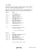
AMX 68000 TARGET GUIDE Table of Contents Page 1. Getting Started with AMX 68000 1.1 1.2 1.3 1.4 1.5 1 Introduction ........................................................................................ AMX Files .......................................................................................... AMX Nomenclature ........................................................................... AMX 68000 Target Specifications ..................................................... Launch Requirements ......
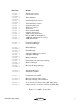
AMX 68000 TARGET GUIDE Table of Contents (Cont'd) Appendices Page Appendix A. Target Parameter File Specification A-1 A.1 Target Parameter File Structure ......................................................... A-1 A.2 Target Parameter File Directives ....................................................... A-3 A.3 Porting the Target Parameter File ...................................................... A-11 Appendix B. AMX 68000 Service Procedures B-1 Appendix C.
1. Getting Started with AMX 68000 1.1 Introduction The AMX™ Multitasking Executive is described in the AMX User's Guide. This target guide describes AMX 68000 which operates on the Motorola MC680xx, MC683xx and all architecturally compatible processors. Throughout this manual, the term M68000 refers specifically to the Motorola MC680xx and MC683xx families of processors and all processors which are exact replicas.
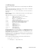
1.2 AMX Files AMX is provided in C source format to ensure that regardless of your development environment, your ability to use and support AMX is uninhibited. AMX also includes a small portion programmed in M68000 assembly language. Figures 1.2-1, 2 and 3 summarize the AMX modules provided with AMX 68000. The AMX product manifest (file MANIFEST.TXT) is a text file which indicates the current AMX revision level and lists the AMX modules which are provided with the product. File Name Module CJ532 .
File Name Module CJ532KA .C CJ532KB .C CJ532KBR.C CJ532KC .C CJ532KCR.C CJ532KD .C CJ532KDR.C CJ532KE .C CJ532KF .C CJ532KG .C CJ532KH .C CJ532KI .C CJ532KJ .C CJ532KK .C CJ532KL .C CJ532KM .C CJ532KX .C Kernel task services General task services CJ532CL .C CJ532LM .C Circular List Manager Linked List Manager CJ532BM .C CJ532BMR.C CJ532EM .C CJ532EMR.C CJ532RM .C CJ532SM .C CJ532SMR.C CJ532MB .C CJ532MBR.C CJ532MF .C CJ532MM .C CJ532MMR.C CJ532MX .C CJ532MXR.C Buffer Manager CJ532TDA.C CJ532TDB.
1.3 AMX Nomenclature The following nomenclature standards have been adopted throughout the AMX Target Guide. Numbers used in this manual are decimal unless otherwise indicated. Hexadecimal numbers are indicated in the format 0xABCD or $ABCD. The terminology A(Table XYZ) is used to define addresses. It is read as "the address of Table XYZ". Read/write memory is referred to as RAM. Read only memory (non-volatile storage) is referred to as ROM.
1.4 AMX 68000 Target Specifications AMX 68000 was initially developed and tested using the Motorola MC68020, MC68040 and MC68332 processors on a variety of Motorola evaluation boards. However, the AMX 68000 design criteria fully encompass the Motorola M68000 processor family requirements. AMX uses a set of design constants which vary according to the constraints imposed by each target processor. When operating on the M68000 processor, these design constants assume the values listed in Figure 1.4-1.
1.5 Launch Requirements The M68000 must be properly configured for use before AMX is launched. The manner in which this is accomplished will depend on your target hardware implementation and on the startup code provided with your C compiler. AMX does not include bootstrap code to initialize the M68000 processor. It is assumed that you will have a boot ROM present which configures the M68000 for your specific hardware configuration and begins program execution at the entry to your C startup code.
Trace Controls AMX alters the state of the status register (SR) whenever it enables or disables interrupts. When AMX disables interrupts, it also clears the trace control bits (T or T0 and T1) to 0. When AMX enables interrupts, the trace control bits remain unaltered. Consequently, you may not be able to use your debugger to single step trace through private AMX code sequences.
Memory Management Unit (MMU) The MC68030, MC68040, MC68LC040 and MC68060 include a Memory Management Unit (MMU) to support a demand-paged virtual memory environment. AMX does not support the M68000 memory management unit. If you are using AMX on the Motorola MC68000, MC68008, MC68010 or MC683xx processors, this restriction does not apply.
2. Program Coding Specifications 2.1 Task Trap Handler AMX 68000 supports task traps for the M68000 zero divide, bounds check and overflow faults. A zero divide fault occurs if any M68000 instruction attempts an integer division by zero. A bounds check fault occurs if the M68000 CHK instruction detects an array bound violation. An overflow fault occurs if the overflow flag (V) is set in the status register (SR) at the time an M68000 TRAPV instruction is executed.
2.2 Task Scheduling Hooks There are four critical points within the AMX Task Scheduler. These critical points occur when: a task is started a task ends a task is suspended a task is allowed to resume. AMX allows a unique application procedure to be provided for each of these critical points. Pointers to your procedures are installed with a call to procedure cjkshook. You must provide a separate procedure for each of the four critical points.
3. The Processor Interrupt System 3.1 Operation The M68000 classifies all internal and external sources of interruption as exceptions. The processor automatically determines the cause of the exception and then branches indirectly through entries in the processor Exception Vector Table to an appropriate exception specific procedure. The particular procedures which service internal or external device interrupt requests are called Interrupt Service Procedures.
Default Exception Service Procedures AMX provides default service procedures for most exceptions. The zero divide, bounds check and overflow exceptions are serviced by AMX using its Task Trap Handler mechanism. All other exceptions handled by AMX are treated as fatal. AMX calls a Fatal Exception Procedure cjksfatalexh in module CJ532UF.C identifying the exception and the machine state at the time of the exception.
3.2 AMX Vector Table The M68000 processor provides an Exception Vector Table, often referred to as the AMX Vector Table, through which device interrupts are vectored and processor faults are trapped. The position of entries in the table and the vector numbers used to reference them are dictated by Motorola. AMX provides a set of cjksixxxx service procedures to allow you to dynamically access or modify entries in the AMX Vector Table.
Vector Name Vector Number 0, 1 2 3 4 5 6 7 8 9 10 11 12 13 14 15 CJ_PRVNRES CJ_PRVNBE CJ_PRVNAE CJ_PRVNII CJ_PRVNZD CJ_PRVNCH CJ_PRVNTV CJ_PRVNPV CJ_PRVNTR CJ_PRVNLA CJ_PRVNLF CJ_PRVNCP CJ_PRVNFE CJ_PRVNUI CJ_PRVNSI 16 to 23 24 25 to 31 CJ_PRVNTT 32 to 47 CJ_PRVNFPBS CJ_PRVNFPIN CJ_PRVNFPDZ CJ_PRVNFPUN CJ_PRVNFPOP CJ_PRVNFPOV CJ_PRVNFPSN CJ_PRVNFPUD 48 49 50 51 52 53 54 55 CJ_PRVNMMCF CJ_PRVNMMOP CJ_PRVNMMAV 56 57 58 59 to 63 64 to 255 Enable Mask $00000004 $00000008 $00000010 $00000020 $0000004
3.3 AMX Interrupt Priority and NMI The M68000 family of processors offers inherent interrupt priority ordering. The AMX Interrupt Supervisor supports this feature and allows the nesting of interrupts for fast response to high priority events. The M68000 interrupt priority mask in the status (SR) register establishes the current interrupt priority. Tasks run at interrupt priority level 0 with all interrupt sources enabled. Some interrupts may be specifically disabled by an external interrupt controller.
3.4 Conforming ISPs A conforming ISP consists of an ISP root and a device Interrupt Handler. The ISP root is created in your Target Configuration Module by the AMX Configuration Generator using the information provided in your Target Parameter File (see Chapter 4). The address of the ISP root must be installed in the AMX Vector Table.
The following examples illustrate how simple an Interrupt Handler can be. /* /* /* /* /* The ISP root definition in the Target Parameter File is as follows:*/ ...ISPC deviceisp,deviceih,26,0,0 */ The ISP root is given the public name deviceisp */ The Interrupt Handler is named deviceih */ The device interrupts on vector number 26 (level 2) */ void CJ_CCPP deviceih(void) { local variables, if required : Clear the source of the interrupt request. Perform all device service.
3.5 Nonconforming ISPs The M68000 family of processors provides an interrupt priority ordering mechanism which permits the use of nonconforming ISPs within an AMX system. Since nonconforming ISPs bypass the AMX Interrupt Supervisor, they cannot make use of any AMX services. Nonconforming ISPs run at the interrupt priority level dictated by the interrupt source. A nonconforming ISP must NOT set the interrupt priority level to any level numerically lower than the level of the interrupt which it is servicing.
3.6 Processor Vector Initialization Whenever an internal or external device interrupt occurs, the M68000 processor unconditionally vectors to a unique memory address determined by an entry in the processor Exception Vector Table. The code located at that address is called an Interrupt Service Procedure. Whenever an exception occurs, the M68000 processor also unconditionally vectors to a unique memory address determined by an entry in the processor Exception Vector Table.
This page left blank intentionally.
4. Target Configuration Module 4.1 The Target Configuration Process Every AMX application must include a Target Configuration Module which defines the manner in which AMX is to be used in your target hardware environment. The information in this file is derived from parameters which you must provide in your Target Parameter File. The Target Parameter File is a text file which is structured according to the specification presented in Appendix A.
Screen Layout Figure 4.1-1 illustrates the Configuration Manager's screen layout once you have begun to create or edit a Target Parameter File. The title bar identifies the Target Parameter File being created or edited. Below the title bar is the menu bar from which the operations you wish the Manager to perform can be selected. Below the menu bar is an optional Toolbar with buttons for many of the most frequently used menu commands. At the bottom of the screen is the status bar.
Menus All commands to the Configuration Manager are available as items on the menus present on the menu bar. The File menu provides the conventional New, Open, Save and Save As... commands for creating and editing your Target Parameter File. It also provides the Exit command. When the Target Configuration Module selector icon is the currently active selector, the Generate... command on the File menu can be used to generate your Target Configuration Module.
If you have modified some of the fields on a property page and then decide that these modified values are not correct, use the Undo Page command on the Edit menu or Toolbar to force the Configuration Manager to restore the content of all fields on the page to the values which were in effect when you moved to that property page. When you go to save your Target Parameter File or prepare to move to another property page, the Configuration Manager will validate all parameters on the page which you are leaving.
4.2 Target Configuration Parameters General Parameters The General Parameter window allows you to define the general operating characteristics of your AMX system within your target hardware environment. The layout of the window is shown in Figure 4.1-1 in Chapter 4.1. CPU Type Identify your processor architecture by selecting a processor from the available list. This parameter is used to condition AMX to accommodate the operating characteristics of a particular processor or architecture.
Vectors in RAM In most cases, the processor Exception Vector Table will be located in alterable RAM at address 0 or at some alternate address provided by you. Therefore check this box. If your processor Exception Vector Table is in ROM, leave this box unchecked. In this case, you must initialize the ROM vector table for AMX use as directed in Chapter 3.6. Vectors Not Alterable Even if the processor Exception Vector Table will be located in RAM, you can still prevent AMX from altering it.
Software I/O Delay AMX provides a device I/O delay procedure cjcfhwdelay which is used by AMX board support modules and sample device drivers to provide the necessary delay between sequential references to a device I/O port. Such delay is often required to accommodate long device access times when operating at very high processor clock frequencies. Check this box to adjust the AMX software delay loop to match your hardware requirements.
Fatal Exceptions The Target Configuration Module defines the processor exceptions which are to be serviced by AMX and treated as fatal. These exceptions are specified by you by checking the appropriate boxes in the Fatal Exception window. The layout of the window is shown below. This example allows AMX to service the bus error, address error, privilege violation, format error, uninitialized interrupt and spurious interrupt exceptions as fatal exceptions.
4.3 Interrupt Service Procedure (ISP) Definitions Your Target Configuration Module must include a device ISP root for each conforming ISP which you intend to use in your application. The ISP roots are constructed for you by the AMX Configuration Builder from ISP descriptions which you enter in the ISP Definition window. The layout of the window is shown below. To add an ISP definition, click on the Add button.
ISP Type At least one of your ISPs must service a clock interrupt which provides AMX with its fundamental clock tick at the frequency and resolution defined in your AMX System Configuration Module. To define your custom clock ISP, choose Clock Handler from the pull down list. An alternate fast clock ISP can be provided by choosing Fast Clock Handler as described in Chapter 4.4. Other AMX clock drivers can be selected from the list presented when you click the Prebuilt Clock ISPs... button.
Interrupt Handler Parameter Your Interrupt Handler can be coded to receive a 32-bit parameter every time it is called. The Parameter Type field is a pull down list used to identify what kind of parameter, if any, your Interrupt Handler expects. If your Interrupt Handler has no need for a parameter, set the Parameter Type to (none). If your Interrupt Handler expects a numeric parameter, set the Parameter Type to Value and enter the required unsigned, 32-bit hexadecimal numeric value into the Parameter field.
4.4 Defining a Fast Clock ISP At least one of your ISPs must service a clock interrupt which provides AMX with its fundamental clock tick at the frequency and resolution defined in your AMX System Configuration Module. For many applications, your clock ISP will just be a standard AMX conforming ISP defined in the ISP Definition window. It is distinguished from all other ISPs by picking Clock Handler as its ISP Type.
ISP Type Your fast clock ISP is identified as such by selecting Fast Clock Handler from the pull down list. ISP Root Edit the default name ---New--- to provide the name you wish to give to your fast clock ISP root. The ISP root name is used to identify your fast clock ISP in the ISP list. The ISP root is a function created by the AMX Configuration Builder in your Target Configuration Module. The function entry point is declared with a public symbol defined with the name you provide.
4.5 Null Functions Occasionally, while developing an AMX application, it can be very convenient to be able to create software functions to satisfy your program link requirements without having to create the final version of these functions. For example, if your AMX System Configuration Module references a Restart Procedure and a task procedure which do not yet exist, you will have to create them in order to successfully link your system. Such functions are called null functions because they do nothing.
4.6 ROM Option Parameters The AMX ROM Option allows the subset of AMX and its managers required by your application to be linked together without any application code to form a separate AMX ROM image. The resulting AMX ROM can be located anywhere in your memory configuration. Your AMX application is then linked with a ROM Access Module which provides access to AMX and its managers in the AMX ROM. The AMX ROM Option Module defines the subset of AMX and its managers which you wish to commit to the AMX ROM.
Enable ROM Option By default, the ROM Option feature is disabled. Check this box to enable the feature. You can disable the feature by removing the check from the box. ROM Address You must define the absolute physical ROM address at which the AMX ROM image is to be located. This address is dictated by you according to your hardware requirements. Enter the address value as an unsigned 32-bit hexadecimal number. The ROM memory address must be long aligned.
5. Clock Drivers 5.1 Clock Driver Operation You must provide a clock driver as part of your AMX application so that AMX can provide timing services. AMX clock drivers are provided with AMX for the timer chips used on the boards with which AMX has been tested. These drivers are ready for use and can be installed as described in Chapter 5.3. An AMX clock driver consists of three parts: an initialization procedure, a clock Interrupt Service Procedure (ISP) and an optional shutdown procedure.
Clock Interrupts A real-time clock used with the M68000 processor will interrupt either on one of the interrupt autovectors or on a user defined vector. In either case, the processor will automatically dispatch through its Vector Table to your clock ISP. The clock ISP consists of an ISP root and an Interrupt Handler. The processor dispatches to the ISP root in response to the clock interrupt request. The ISP root calls the clock Interrupt Handler to dismiss the clock interrupt request.
5.2 Custom Clock Driver The easiest way to create a custom clock driver is by example. Assume that the counter/timer which you intend to use for your AMX clock is characterized as follows: The I/O base address of the clock is at 0xFFA00100. The clock interrupt is generated using vector number 25. The clock interrupt is dismissed by writing bit pattern 0x08 to the clock register at its base address plus 4.
The clock initialization procedure for this custom clock driver could be coded in C as follows. Insert procedure clockinit into your list of Restart Procedures provided in your System Configuration Module at the point at which you wish the clock to be enabled during the launch.
5.3 AMX Clock Drivers AMX clock drivers are provided with AMX for the timer chips used on the boards with which AMX has been tested. These drivers are ready for use as described in this chapter. The clock drivers are delivered in chip support source files having names of the form CHnnnnT.C where nnnn identifies the particular clock chip. The clock chip support procedures are named chxxxxxxx. 5.3.
5.3.2 MC68360 PIT Clock Driver The AMX clock driver for the Motorola MC68360 Periodic Interval Timer (PIT) is ready for use on the Motorola M68360QUADS Application Development System board. It is configured to operate at approximately 1 KHz (1 ms period). Source code for this AMX clock driver is provided in file CH68360T.C. You must compile clock source module CH68360T.C and link the resulting object module with the rest of your AMX application.
5.3.3 MC68230 Clock Driver The AMX clock driver for the Motorola MC68230 Parallel Interface/Timer is ready for use on the Motorola M68EC040 Integrated Development Platform (IDP). It is configured to operate at approximately 1 KHz (1 ms period). Source code for this AMX clock driver is provided in file CH68230T.C. You must compile clock source module CH68230T.C and link the resulting object module with the rest of your AMX application.
5.3.4 MC68901 Clock Driver The AMX clock driver for the Motorola MC68901 Multi-Function Peripheral is ready for use on the Motorola MVME133 VMEmodule board. It is configured to use timer A operating at 1 KHz (1 ms period). Source code for this AMX clock driver is provided in file CH68901T.C. You must compile clock source module CH68901T.C and link the resulting object module with the rest of your AMX application.
Appendix A. Target Parameter File Specification A.1 Target Parameter File Structure The Target Parameter File is a text file structured as illustrated in Figure A.1-1. This file can be created and edited by the AMX Configuration Manager, a Windows® utility provided with AMX. ; AMX Target Parameter File : ...LAUNCH PERM,VNA ...HDW PROC,VMASK,VBR,EVTROM,CACHE ...VBASE VTABLE ...DELAY CPUFREQ ; ; Null Functions (optional; one line for each null function) ...
The Target Parameter File consists of a sequence of directives consisting of a keyword of the form ...XXX beginning in column one which is usually followed by a parameter list. Some directives require only a keyword with no parameters. Any line in the file which does not begin with a valid keyword is considered a comment and is ignored. It is the purpose of this appendix to specify all AMX 68000 directives by defining their keywords and the parameters, if any, which they require. The example in Figure A.
A.2 Target Parameter File Directives The AMX Launch Parameters are defined as follows. ...LAUNCH PERM VNA PERM,VNA 0 if the AMX launch is temporary 1 if the AMX launch is permanent 0 if the AMX Vector Table entries are to be alterable 1 if the AMX Vector Table entries are NOT to be alterable You must set VNA to 0 to allow AMX or your application to dynamically install exception handlers into the AMX Vector Table at run time. If you set VNA to 0, you must also set EVTROM to 0 in the ...HDW keyword entry.
Vector Base Register The VBR parameter is used to specify the memory address at which the Exception Vector Table is located. For most applications, the Exception Vector Table is located at address 0. You can use the VBR parameter to redefine the location of the Exception Vector Table or to define its location in ROM. At launch, AMX installs the address specified by parameter VBR into the processor's Vector Base Register (VBR), if one exists for the processor specified by parameter PROC.
Device I/O Delay The Target Parameter File includes a device I/O delay definition. ...DELAY CPUFREQ CPUFREQ M68000 processor instruction execution frequency (MHz) The ...DELAY directive allows you to condition the delay loop of the AMX device I/O delay procedure cjcfhwdelay to match your hardware requirements. This directive allows AMX to use your estimate of the processor's instruction execution frequency defined by parameter CPUFREQ to derive the loop count needed to provide a one microsecond delay.
Conforming ISP Declarations The Target Parameter File must include a definition of an ISP root for each conforming Interrupt Service Procedure (ISP) which you intend to use in your application. The ISP root definition is provided using one of the following directives. The ISP root is declared using ...ISPC if its Interrupt Handler is coded in C or ...ISPA if its Interrupt Handler is coded in assembly language. ...ISPC ...
AMX Clock Handler Declaration The Target Parameter File must include a definition of an ISP root for your AMX clock handler. The clock ISP root definition must be provided using one of the following directives. The clock ISP root is declared using ...CLKC if its Interrupt Handler is coded in C or ...CLKA if its Interrupt Handler is coded in assembly language. The clock ISP root can be declared using ...CLKFAST if an Interrupt Handler is not required to service the clock.
If your clock can be serviced by writing one or two n-bit values to a device I/O port, you can use the ...CLKFAST directive to create a very fast clock ISP root with no application code required. The general form of the ...CLKFAST directive is as follows. ...
AMX ROM Option To use the AMX ROM option, the Target Parameter File must include the following directives. ...ROMOPT ...ROMSM ...ROMEM ...ROMMB ...ROMMX ...ROMBM ...ROMMM ...ROMCL ...ROMLL ...ROMTD ROMADR,RAMADR ;Semaphore Manager ;Event Manager ;Mailbox Manager ;Message Exchange Manager ;Buffer Manager ;Memory Manager ;Circular List Manager ;Linked List Manager ;Time/Date Manager Parameter ROMADR is the absolute physical ROM address at which the AMX ROM image is to be located.
This page left blank intentionally.
A.3 Porting the Target Parameter File It is expected that you will use the AMX Configuration Manager to create and edit your Target Parameter File. If you are unable to use the AMX Configuration Manager utility, you will have to create and edit your Target Parameter File using a text editor. You should begin by choosing one of the sample Target Parameter Files provided with AMX.
This page left blank intentionally.
Appendix B. AMX 68000 Service Procedures B.1 Summary of Services AMX 68000 provides a collection of target dependent AMX service procedures for use with the M68000 processor and compatibles and the C compilers which support them. These procedures are summarized below.
The AMX Library also includes several C procedures which are used privately by KADAK. These procedures, although available for your use, are not documented in this manual and are subject to change at any time. The procedures are briefly described in source file CJZZZUB.ASM. Prototypes will be found in file CJZZZIF.H. The register array structure cjxregs which they use is defined in file CJZZZKT.H.
B.2 Service Procedures A description of all processor dependent AMX 68000 service procedures is provided in this appendix. The descriptions are ordered alphabetically for easy reference. Italics are used to distinguish programming examples. Procedure names and variable names which appear in narrative text are also displayed in italics. Occasionally a lower case procedure name or variable name may appear capitalized if it occurs as the first word in a sentence.
Interrupts AMX procedures frequently must deal with the processor interrupt mask. The effect of each AMX procedure on the interrupt state is defined according to the following legend.
cjcfccsetup cjcfccsetup Purpose Setup C Environment Used by n Setup Prototype is in file CJZZZIF.H. #include "CJZZZ.H" void CJ_CCPP cjcfccsetup(void); Description Use cjcfccsetup to setup all low level processor registers to meet the requirements of a particular C compiler. For example, the C compiler may assume that some data variables can be accessed using a particular register which always points to the data.
cjcfdi cjcfei cjcfdi cjcfei Purpose Disable or Enable Interrupts Used by n Setup Prototype in file CJZZZTF.H or macro #include "CJZZZ.H" void CJ_CCPP cjcfdi(void); void CJ_CCPP cjcfei(void); Description Tasks can use cjcfdi to briefly disable all sources of interrupt. Immediately thereafter the task can use cjcfei to enable all sources of interrupt again.
cjcfflagrd cjcfflagwr cjcfflagrd cjcfflagwr Purpose Read or Write Processor Status Register Used by n Setup Prototype in file CJZZZTF.H or macro in file CJZZZCC.H. #include "CJZZZ.H" CJ_TYFLAGS CJ_CCPP cjcfflagrd(void); void CJ_CCPP cjcfflagwr(CJ_TYFLAGS flags); Description Cjcfflagrd Task n ISP n Timer Procedure n Restart Procedure n Exit Procedure returns the actual state of the processor status register (SR). Cjcfflagwr updates the processor parameter flags to the register.
cjcfhwdelay cjcfhwdelay Purpose Delay n Microseconds Used by n Setup Prototype is in file CJZZZIF.H. #include "CJZZZ.H" void CJ_CCPP cjcfhwdelay(int n); Description n Task n n ISP Timer Procedure n Restart Procedure n Exit Procedure is the delay interval measured in microseconds. Use cjcfhwdelay to generate a software delay loop of approximately n microseconds.
cjcfhwbcache cjcfhwdcache cjcfhwicache cjcfhwbcache cjcfhwdcache cjcfhwicache Purpose Flush and Enable/Disable Caches Used by n Setup Prototype in file CJZZZIF.H. #include "CJZZZ.H" void CJ_CCPP cjcfhwbcache(int operation); void CJ_CCPP cjcfhwdcache(int operation); void CJ_CCPP cjcfhwicache(int operation); Description operation = 0 to force the caches to be flushed and disabled. operation = 1 to force the caches to be flushed and enabled.
cjcfin8 cjcfin16 cjcfin32 cjcfin8 cjcfin16 cjcfin32 Purpose Read an 8, 16 or 32-Bit Input Port Used by n Setup Prototype in file CJZZZTF.H or macro in file CJZZZCC.H. #include "CJZZZ.H" CJ_T8 CJ_CCPP cjcfin8(void *port); CJ_T16 CJ_CCPP cjcfin16(void *port); CJ_T32 CJ_CCPP cjcfin32(void *port); Description port Interrupts o Returns Cjcfin8 returns an 8-bit signed value. Cjcfin16 returns a 16-bit signed value. Cjcfin32 returns a 32-bit signed value. Example #include "CJZZZ.
cjcfjlong cjcfjset Purpose cjcfjlong cjcfjset cjcfjset Sets a Mark for a Long Jump cjcfjlong Long Jumps to that Mark These procedures are provided for AMX portability. They are not replacements for C library procedures longjmp or setjmp although they function in a similar manner. Used by n Setup Prototype is in file CJZZZTF.H. #include "CJZZZ.
Example #include "CJZZZ.
cjcfmcopy cjcfmset Purpose cjcfmcopy cjcfmset Copy a Block of Memory Set (Fill) a Block of Memory These procedures are provided for AMX portability. replacements for C library procedures memcpy or memset. They are not Used by n Setup Prototype is in file CJZZZTF.H. #include "CJZZZ.
cjcfout8 cjcfout16 cjcfout32 cjcfout8 cjcfout16 cjcfout32 Purpose Write to an 8, 16 or 32-Bit Output Port Used by n Setup Prototype in file CJZZZTF.H or macro in file CJZZZCC.H. #include "CJZZZ.
cjcfstkjmp Purpose cjcfstkjmp Switch Stacks and Jump to a New Procedure This procedure is provided for AMX portability. Used by n Setup Prototype is in file CJZZZTF.H. #include "CJZZZ.H" void CJ_CCPP cjcfstkjmp(void *vp, void *stackp, CJ_VPPROC procp); Description vp o Task o ISP Timer Procedure o Restart Procedure n Exit Procedure is a pointer which is passed as a parameter to the new procedure. is a pointer to a properly aligned block of memory for use as a stack.
cjcftag cjcftag Purpose Convert a String to an Object Name Tag Used by n Setup Prototype is in file CJZZZTF.H. #include "CJZZZ.H" CJ_TYTAG CJ_CCPP cjcftag(char *tag); Description tag Interrupts o Returns Task n n ISP Timer Procedure n Restart Procedure n Exit Procedure is a pointer to a string which is a one to four character name tag. Disabled o Enabled o Restored The name tag string is converted to a 32-bit name tag value of type which is returned to the caller.
cjcfvol8 cjcfvol16 cjcfvol32 cjcfvolpntr Purpose cjcfvol8 cjcfvol16 cjcfvol32 cjcfvolpntr Fetch a Volatile 8-Bit, 16-Bit, 32-Bit or Pointer Value Use these procedures to fetch the content of a volatile variable if the C compiler does not support the C keyword volatile. These procedures (or macros) also guarantee that multiple byte fetches will be done in an indivisible fashion. Used by n Setup Prototype in file CJZZZTF.H or macro in file CJZZZCC.H. #include "CJZZZ.
This page left blank intentionally.
cjksitrap cjksitrap Purpose Install a Task Trap Handler Used by n Setup Prototype is in file CJZZZIF.H. #include "CJZZZ.H" CJ_ERRST CJ_CCPP cjksitrap(int trapid, CJ_TRAPPROC handler); Description trapid Task o o ISP Timer Procedure o Restart Procedure n Exit Procedure is the processor vector number which identifies the particular error trap.
cjksivtp B-20 cjksivtp Purpose Fetch Pointer to the AMX Vector Table Used by n Setup Prototype is in file CJZZZIF.H. #include "CJZZZ.H" void * CJ_CCPP cjksivtp(void); Interrupts o Returns A pointer to the AMX Vector Table.
cjksivtrd cjksivtrd Purpose Read from the AMX Vector Table Used by n Setup Prototype is in file CJZZZIF.H. #include "CJZZZ.H" CJ_ERRST CJ_CCPP cjksivtrd(int vector, CJ_ISPPROC *oldproc); Description vector Task n n ISP Timer Procedure n Restart Procedure n Exit Procedure is the processor vector number (0 to 255). Vectors 12, 16 to 23 and 59 to 63 are reserved by Motorola.
cjksivtwr cjksivtwr Purpose Write to the AMX Vector Table Used by n Setup Prototype is in file CJZZZIF.H. #include "CJZZZ.H" CJ_ERRST CJ_CCPP cjksivtwr(int vector, CJ_ISPPROC newproc); Description vector Task n n ISP Timer Procedure n Restart Procedure n Exit Procedure is the processor vector number (0 to 255). Vectors 12, 16 to 23 and 59 to 63 are reserved by Motorola. newproc is a pointer to the new Interrupt Service Procedure. Interrupts o Returns Error status is returned.
cjksivtx cjksivtx Purpose Exchange an Entry in the AMX Vector Table Used by n Setup Prototype is in file CJZZZIF.H. #include "CJZZZ.H" CJ_ERRST CJ_CCPP cjksivtx(int vector, CJ_ISPPROC newproc, CJ_ISPPROC *oldproc); Description vector Task n n ISP Timer Procedure n Restart Procedure n Exit Procedure is the processor vector number (0 to 255). Vectors 12, 16 to 23 and 59 to 63 are reserved by Motorola. newproc is a pointer to the new Interrupt Service Procedure.
This page left blank intentionally.
Appendix C. AMX 68000 ROM Option An AMX system can be configured in two ways. The particular configuration is chosen to best meet your application needs. Most AMX systems are linked. Your AMX application is linked with your System Configuration Module, your Target Configuration Module and the AMX Library. The resulting load module is then copied to memory for execution either by loading the image into RAM or by committing the image to ROM.
Creating an AMX ROM The AMX ROM is created by using the AMX Configuration Generator to produce a ROM Option Module which is then linked with the AMX Library to form an AMX ROM image. The Configuration Generator combines the information in your Target Parameter File with the ROM Option Template file CJ532ROP.CT to produce an assembly language ROM Option Module CJ532ROP.ASM. You can use the AMX Configuration Builder to generate the ROM Option Module.
Linking for AMX ROM Access The AMX Configuration Generator is used to produce a ROM Access Module which, when linked with your application, provides access to AMX in the AMX ROM. The Configuration Generator combines the information in your Target Parameter File with the ROM Access Template file CJ532RAC.CT to produce an assembly language ROM Access Module CJ532RAC.ASM. You can use the AMX Configuration Builder to generate the ROM Access Module.
Once linked, your AMX application can be downloaded into RAM memory in your target hardware configuration. Alternatively, your application can be transferred to ROM using the same techniques that were used to produce the AMX ROM. Regardless of the manner in which your AMX system is loaded into your target hardware, access to the AMX ROM via the ROM Access Module is now possible. For simplicity, the complexities which you will encounter when trying to commit the C Runtime Library to ROM have been ignored.