Instruction Manual Novara 3000 Series ControlPads CP-3006, CP-3008, CP-3017-NA, CP-3017-TR-US ControlPads L a s t R e v is e d : 7 / 2 2 / 2 0 1 4
AMX DOMESTIC CHANNEL PARTNER and END CUSTOMER LIMITED WARRANTY, DISCLAIMER AND LICENSE (Excerpt from CHANNEL PARTNER TERMS AND CONDITIONS Versions 11.17.2011 with updates for previous version 8.25.2010 [sections 6.1 (a), (b) and (f)]) Definitions “End Customer” means an authorized end customer with direct in warranty privileges from AMX. Within this limited warranty, disclaimer and license document, “End Customer” shall have the same meaning as “Channel Partner” with the noted exceptions of Sections 6.
Table of Contents Table of Contents NOVARA 3000 Series ControlPads .....................................................................1 Overview .................................................................................................................. 1 Product Specifications .............................................................................................. 2 CP-3006........................................................................................................................
Table of Contents Button Labeling ................................................................................................19 Overview ................................................................................................................ 19 Installing Acetate Button Labels and Key Caps - READ THIS FIRST!.............................. 19 Removing/Replacing Button Labels ........................................................................ 21 Disassembling the NOVARA ControlPad..........
Table of Contents Lockout Buttons ............................................................................................................ 46 Bank Enable................................................................................................................... 47 Advance Toggle ............................................................................................................ 48 Button Actions and Events ..................................................................................
Table of Contents iv Novara 3000 Series ControlPads Instruction Manual
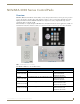
NOVARA 3000 Series ControlPads NOVARA 3000 Series ControlPads Overview NOVARA 3000 Series ControlPads offer the ability to easily control presentation devices such as projectors, projection screens, video displays, and other audio visual equipment as well as a variety of serial or IR-controllable devices like lighting and window treatments. NOVARA ControlPads are designed to be easily configurable allowing control of equipment by RS232 commands and IR.
NOVARA 3000 Series ControlPads Product Specifications CP-3006 NOVARA CP-3006 ControlPad Power Requirements: • Min: 109mA@12 VDC • Max: 220mA@12 VDC • Using a non-PoE power supply operates on voltages ranging from 9V to 16V continuously.
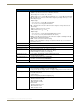
NOVARA 3000 Series ControlPads NOVARA CP-3008 ControlPad Specifications (Cont.) Rear Panel Connectors: • Power - 1 2-pin Phoenix connector accepting 12VDC power • Serial - 2 3-pin Phoenix connectors for RS-232 connections. Input voltage: VIH > +2.7 VDC, VIL < -2.7 VDC Output voltage: VOH > +5.0 VDC @ 35 mA maximum, VOL < -5.0 VDC @ 35 mA maximum • IR - 2 2-pin Phoenix connectors for IR emitters. Supports generating carriers up to 1.142 MHz. Output only port. Output voltage: VOH = +3.3 VDC +/- 0.
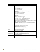
NOVARA 3000 Series ControlPads NOVARA CP-3017-TR-US & -NA ControlPads Specifications (Cont.) Rear Panel Connectors: • Power - One 2-pin Phoenix connector accepting 12VDC power • Serial - Three 3-pin Phoenix connectors for RS-232 connections Input voltage: VIH > +2.7 VDC, VIL < -2.7 VDC Output voltage: VOH > +5.0 VDC @ 35 mA max VOL < -5.0 VDC @ 35 mA max • IR - Two 2-pin Phoenix connectors for IR emitters. Supports generating carriers up to 1.142 MHz. Output only port. Output voltage: VOH = +3.
NOVARA 3000 Series ControlPads Mounting Specifications - 6-Button ControlPads CP-3006 CP-3006 6-button keypads mount onto standard 1 gang US, UK, or EU back boxes. FIG.
NOVARA 3000 Series ControlPads Mounting Specifications - 8-Button ControlPads CP-3008 CP-3008 8-button keypads mount onto standard 2 gang US, UK, or EU back boxes. FIG.
NOVARA 3000 Series ControlPads Mounting Specifications - 17-Button ControlPads CP-3017-TR-US CP-3017-TR-US 17-button keypads mount onto standard 4 gang US back boxes. Reset button access FIG.
NOVARA 3000 Series ControlPads CP-3017-NA CP-3017-NA 17-button keypads mount onto standard 2 gang US, UK, or EU back boxes. FIG.
NOVARA 3000 Series ControlPads Button Layout This section displays the button layout for each type of ControlPad. CP-3006 FIG. 6 CP-3006 button layout CP-3008 FIG. 7 CP-3008 button layout CP-3017-NA FIG.
NOVARA 3000 Series ControlPads CP-3017-TR-US Reset button access FIG.
Wiring and Device Connections Wiring and Device Connections Overview This section describes the device connectors and ports available on each type of NOVARA 3000-series ControlPad. Here you can find wiring and electrical capacities for each type of connector. FIG. 10 displays the rear panel of the CP-3006: Power POWER + - IR G IR IR Port G LAN Port Serial Port G N D R X T X SERIAL FIG. 10 CP-3006 rear panel FIG.
Wiring and Device Connections The CP-3017-NA ControlPad has an identical rear panel layout as the CP-3008 except that the CP-3017-NA contains a third RS-232 port. FIG. 12 displays the rear panel of the CP-3017-TR-US: RS232 ports Relay ports IR ports Power LAN port I/O port FIG. 12 CP-3017-TR-US rear panel Rear Panel Components The following sub-sections describe each component on the rear panel of the 3000-series ControlPads.
Wiring and Device Connections RELAYS You can connect up to two independent external relay devices to the Relay connectors on the device. Connectors labeled A are for Common and B are for Output (FIG. 15). FIG. 15 RELAYS connectors Each relay is isolated and normally open. 24 VDC @ 1 A maximum 28 VAC @ 1 A maximum I/O The I/O port (FIG. 16) responds to switch closures and voltage level (high/low) changes, or can be used for logic-level outputs.
Wiring and Device Connections Output only port. Output voltage is as follows: VOH = +3.3 VDC +/- 0.3 VDC @ 13 mA maximum VOL = 0 VDC +/- 0.3 VDC @ 13 mA maximum The IR/Serial connector wiring specifications are listed in the following table. IR Connector Wiring Specifications (per Port) IR connections Signal Function 1 GND (-) Signal GND Signal 1 (+) IR data GND (-) Signal GND Signal 2 (+) IR data 2 Do NOT connect a power connector to either IR port. Doing so may damage the ControlPad.
Wiring and Device Connections Resetting the ControlPad Each ControlPad features a pinhole Reset pushbutton on the rear on the unit for factory reset. To reset the ControlPad, press and hold in the Reset pushbutton for 10 seconds, then release it. The ControlPad will reset. During factory reset, the backlight turns off for all buttons, but all buttons should be back online after 1-2 minutes. If you do not hold in the reset button for the full 10 seconds, the reset does not occur.
Wiring and Device Connections Button Functions You can create a CP-3000 script for each button on the remote to perform a specific task when pressed. The buttons can be programmed by using AMX DCS software to program a virtual button. Each button has a corresponding IR remote code. See the IR Remote Codes section for a list of IR remote codes. To program a button function, write a script for a virtual button numbered with the corresponding IR remote code for the button on the remote plus 100.
Wiring and Device Connections PS-PoE-EX0.9 PoE Extractor The PS-PoE-EX0.9 PoE Extractor (FG423-85) (FIG. 22) is a power extractor module that delivers regulated DC power for any secondary device that is not Power-over-Ethernet (PoE) capable. It allows multiple PoE devices to run over a single power over Ethernet. LAN output LAN input Power output FIG. 22 PS-PoE-EX0.9 PoE Extractor Product Specifications PS-PoE-EX0.
Wiring and Device Connections Connection The PS-PoE-EX0.9 PoE Extractor converts a LAN connector PoE source into a data-only LAN output and a voltageonly output via a standard DC connector. Use standard Cat5 cables and the provided power connector to connect the PoE Extractor to your ControlPad. To LAN port on ControlPad To Power input on ControlPad FIG. 23 PoE Extractor outputs The following steps describe how to connect the PoE Extractor to your ControlPad. 1.
Button Labeling Button Labeling Overview NOVARA ControlPads and KeyPads come with a set of clear plastic Key Caps, which are designed to fit tightly over the pushbuttons, and allow you to place a label on each button according to the requirements of your particular installation. NOVARA ControlPads and KeyPads also come with a pre-printed acetate sheet with a range of 50 (pre-cut) button label inserts.
Button Labeling Key Cap - tilted so that the bottom of the Cap is placed on the bottom of the pushbutton first Clip At this point, do not allow the clips on the sides of the Key Cap to engage 1 Clip Pushbutton on keypad Press the top of the Key Cap down to engage both clips at once, securing the Key Cap to the pushbutton Once the clips are engaged, the Key Cap is secured to the pushbutton 2 3 FIG.
Button Labeling Removing/Replacing Button Labels The button labels on NOVARA keypads are acetate inserts that fit inside the Key Caps installed on the pushbuttons. In order to change the inserts, the key caps need to be removed.
Button Labeling CP-3008 Reassembly FIG. 29 CP-3008 reassembly CP-3017-NA Reassembly FIG.
Button Labeling CP-3017-TR-US Reassembly FIG.
Button Labeling 24 Novara 3000 Series ControlPads Instruction Manual
Device Configuration Software Device Configuration Software Overview You can configure Novara ControlPads and KeyPads using the AMX DCS software application, available for download from www.amx.com (FIG. 32). FIG. 32 AMX DCS Main screen The AMX DCS application allows the ControlPad to perform various functions such as RS232/IR control, button feedback, delay time, and relay control. Each button is configured individually, and can execute on a Press or Release.
Device Configuration Software You may experience scaling issues with the AMX DCS user interface if you use Large or Extra Large fonts with a low resolution display. Adjusting your resolution to a standard DPI setting should resolve these issues. Setting Your Bonjour Preference Bonjour is a zero-configuration networking client that allows you to detect the IP addresses of any ControlPads on a local area network. In essence, it allows you to set up a network without any configuration.
Device Configuration Software Project Device Configuration The project device configuration establishes the layout of all devices in the system. When you open an existing project device configuration, AMX DCS detects all devices on the network. Any devices found appear in the Devices Found on Network area. You can use these devices to create a layout of devices, separating each by project or location. You can create your device layout in the Device Configuration Layout & Inspector window (FIG. 35).
Device Configuration Software Device Configuration Layout & Inspector Window Options (Cont.) Device Settings Click to view the Network, Device Info, DNS, and Connection settings for a device. At the device level, you can set individual settings for a single device or use the global device settings set for the project. This button only appears when you select a device in the device layout. Cut Device Click to remove a node from the device layout and save it to memory.
Device Configuration Software FIG. 36 Modify Layout Device Information window 3. Enter the name for the ControlPad in the Layout Name field. If you have a CP-3006 with a serial number (located under the barcode) of 123456APX78A0001, the hostname and the device name that will be used by its Bonjour beacon will be AMX-CP-3006-123456APX78A0001. For models with a designation such as CP-3017-TR, the hostname will include the -TR (e.g. AMX-CP-3017-TR-123456APX78A0001). 4.
Device Configuration Software Adding a Node to the Device Layout Add a Project node to an empty device layout by clicking the Add button. The project node automatically appears and you can rename the project to anything you like. After naming the project, you can configure the global settings for the project. See the Configuring Global Settings section on page 30 for more information.
Device Configuration Software The following table lists the options for each section of the Configure Global Device Settings window: Configure Global Device Settings Window Options Network Enable DHCP Enables DHCP on all devices when checked. This option is checked by default. This option is checked by default. If you disable this option, you should manually configure static IP addresses for the ControlPads in the Device Info section of the Configure Device Settings window.
Device Configuration Software Configure Global Device Settings Window Options (Cont.) Web Enable HTTP Web Server Enables the HTTP web server on all devices when checked. This option is unchecked by default. This option enables access to web pages for all devices. See the Web Console section on page 63 for more information on the web pages. Administrator Name Enter the web server administrator name in this field. The default administrator name is Admin and is populated in the field by default.
Device Configuration Software The following table lists the options for the Device Info screen. You must configure these options if you disable DHCP in the Configure Global Device Settings window. Configure Device Settings Window Options Retrieve Data from Device Click this button to retrieve information about the ControlPad. Clicking the button opens the Retrieve Device Information window. New Device Name Enter the new name for the device in the provided field.
Device Configuration Software Clicking a button on the device interface changes the event button number here. FIG. 40 Button area Device Setup The following sections describe the options available for event scripting for each keypad. Scripting The Scripting area enables you to program a series of events and upload the program to the device. In this area, you can view the script as it currently exists, and add, delete, or re-arrange the order of events as needed.
Device Configuration Software Scripting Options (Cont.) Copy Click to copy the selected events into memory. This button appears grayed-out until you select an event within the script. These events can be viewed by clicking Clipboard. Paste Click to place the events on the current clipboard into the script. The events are inserted at the end of the script. To insert the events into another part of the script, use the Insert button.
Device Configuration Software Setup Setup contains five options for your ControlPad: Button Backlight, Button Behavior, Button Groups, Volume Control, and Interrogation. Click the plus sign (+) beside Setup to expand or collapse the available options. Button Backlight The Button Backlight option enables you to set the backlight color and level for each button on the keypad. Select a button on the graphical representation of the keypad then select Button Setup to change the button backlight properties.
Device Configuration Software Button Behavior A button can be assigned to one of four banks W, X, Y, or Z. Each bank can have up to four different functions. This is useful if you have a common set of functions. For example, you could have a single 'Play' button controlling up to four different devices (e.g. DVD, VCR, CD, MP3 player, etc). To achieve this, you must enable a bank and assign a Play command to one or more buttons, and then assign the entire bank to another button. FIG.
Device Configuration Software To assign a button to a button group: 1. Open the AMX DCS window. 2. Select Button Groups in the Content area. The Button Groups options appear (FIG. 46). 3. Click Assign Button Grouping. The Button Grouping dialog opens (FIG. 47). FIG. 47 Button Grouping dialog 4. Use the Button # - Assigned Name options menu to select a ControlPad button. 5. Click the appropriate Group check boxes to assign the selected ControlPad button to a group.
Device Configuration Software 3. Use the Maximum Value slider to set the maximum volume for the device. 4. Use the Default Value slider to set the default volume for the device. 5. In the Scripting area, click Program Devices. The volume settings are sent to the ControlPad. If you attempt to program the volume with an empty script, the ControlPad does not reflect the change. You must program at least one line of a script for the new volume settings to take effect.
Device Configuration Software 5. Use the Device Model menu to indicate the specific device connected to the port. If you do not see the device, you may need to add it to the Device Library. See the Adding a Device to the Device Library section on page 56 for more information. In the AMX DCS window, click Tag Data to open the Device Interrogation window (FIG. 51) and view the details of the device. FIG.
Device Configuration Software FIG. 52 Assign RMS Custom Request and Status Names window Perform these steps to change the custom request and status names for RMS: 1. In the AMX DCS window, click the plus sign (+) beside Setup in the Content area. A list of setup options appear. 2. Click Interrogation. The Device Interrogation options appear (FIG. 49). 3. Click RMS/Settings. The Assign RMS Custom Request and Status Names window opens (FIG. 52). 4.
Device Configuration Software Buttons Options Action Enables you to indicate whether you want to activate button feedback. You can choose from On, Backlight, Flash, Full Off, On / All Buttons Off, On / Group Off, On / All Buttons Backlight, and On / Group Backlight. Selecting Full Off turns off button feedback and reduces LED power to zero. Selecting Group Off or Group Backlight sets the event for all buttons assigned to a button group. See the Button Groups section on page 37 for more information.
Device Configuration Software FIG. 55 RS232 options The following table lists the RS232 options: RS232 Options Device Model Enables you to select the device connected to the RS232 port on the ControlPad. If no devices are available from the drop-down menu, click Select Device to select and load a device. If no devices are available, click Device Library to add a device. See the Device Library Manager section on page 54 for more information.
Device Configuration Software If the Make and Type fields are blank, you need to use the Device Library Manager to create or import devices. See the Adding a Device to the Device Library section on page 56 and the Importing a Device Library section on page 57 for more information. 5. Click Load Devices to close the dialog and return to the AMX DCS window. You should now see the Device Model and Function menus populated with one or more options. 6.
Device Configuration Software 2. Click Load IR File for Selected Port. An Open dialog appears with which you can navigate to the location of an AMX IR file (.irl) containing information about your IR device. After you have selected the appropriate file, click OK. 3. Select the IR port the device is connected to from the Port options menu. 4. Select a function from the Function Code options menu. 5. Select the number of times you want the function to occur from the Action menu.
Device Configuration Software Delay The Delay option enables you to insert a period of inaction into a script. Delays can range from 1 second up to 9 minutes and 59 seconds. The delay is absolute and no other Event or Button press is acknowledged until the time period has elapsed. FIG. 60 Delay options The following table lists the Delay options: Delay Options Minutes Use the slider to indicate the number of minutes in the delay. You can set up to 9 minutes.
Device Configuration Software Lockout Buttons Options (Cont.) Delete Click to remove the selected a button from the button combination. Clear Click to remove all buttons from the button combination. Combination Button Press Displays the current button combination. Perform these steps to set a button lockout: 1. In the AMX DCS window, click Lockout Buttons. The Lockout Buttons options appear (FIG. 61). 2.
Device Configuration Software 17. Click Add to add the event to the script. 18. Select Green from the Color menu, and select 2 from the Bank Level menu on the right side of the window. 19. Click Add to add the event to the script. 20. Select Blue from the Color menu, and select 3 from the Bank Level menu on the right side of the window. 21. Click Add to add the event to the script. 22. Select Yellow from the Color menu, and select 4 from the Bank Level menu on the right side of the window. 23.
Device Configuration Software 10. Select Red from the Color menu, and select 1 from the Toggle Level menu on the right side of the window (FIG. 65). Toggle Level menu FIG. 65 Toggle Level menu 11. Click Add to add the event to the script. 12. Select Green from the Color menu, and select 2 from the Toggle Level menu on the right side of the window. 13. Click Add to add the event to the script. 14. Click Button 3 on the ControlPad interface. 15.
Device Configuration Software Button Actions and Events The Button area enables you to specify whether a button event occurs when the button is pressed or the button is released. You can also use this area to assign a name to a button or create custom names for devices. FIG.
Device Configuration Software FIG. 67 Custom Assigned Button Name dialog 2. Enter a device ID number within the range of 2000-65536 in the RMS Unique ID field. If you enter a number outside the device ID range, an error message appears. 3. Enter a name for the button in the Assigned Name field. 4. Click Save. The dialog closes and the custom button appears in the Button Assigned Name options menu.
Device Configuration Software Creating a Schedule Script A schedule script is a script which executes at a scheduled time. Once you set up a scheduled time, you can add events to the selected schedule script. FIG. 70 Schedule script Perform these steps to create a schedule script: 1. In the Script Types area, click Schedule. A set of options appears in the blank space within the area (FIG. 70). 2. Click Add. The Schedule Properties window opens (FIG. 71). FIG. 71 Schedule Properties window 3.
Device Configuration Software FIG. 73 Timeout Properties dialog 3. Use the Hours and Minutes menus to indicate the length of the timeout. 4. Click Save to return to the AMX DCS window. 5. Select the timeout from the Timeout menu and create a script. When you program the device, the script will execute after the specified amount of time elapses without any activity on the ControlPad.
Device Configuration Software If you open a device with a script already programmed or working, but you just want to set the button setup (backlight) color, you must also re-program the script. Failure to program the script again may result in the device rebooting, and programming the device configuration without the new button setup being transmitted to the device. Perform these steps to program a device: 1. Open the Device Configuration & Layout Inspector window (see page 27). 2.
Device Configuration Software The following options appear on the Device Library Manager window Device Library Manager Options Device Selection Device Filter The Device Filter option opens to reveal three filtering options to help narrow your search for a specific device. You can filter by Manufacturer, Device Type, or Communications. Add Add a new device to the library. The Manufacturer can be a new manufacturer or you can select a previously-defined entry from the drop-down list.
Device Configuration Software Device Library Manager Options (Cont.) Paste Once a selected record from the command/status table is cut or copied, click this button to paste the record into any model’s command/status table (provided the name is unique.) Test Command Click to launch the Test Command Tool so you can send commands and view feedback from the receiving device.
Device Configuration Software 7. Click Save to save the Device Library. DCS will add default fields when you create a new custom library file. Modifying Devices in the Device Library To modify a device's connection and command information, perform the following steps: 1. Select the device from the Device Selection tree. Its connection and command information appears in the right pane. 2.
Device Configuration Software 2. Right-click the device with undefined fields, and select Rename Device(s). The Rename Device Libraries dialog opens (FIG. 78). FIG. 78 Rename Device Libraries dialog 3. Enter the appropriate information in the undefined fields. 4. Click Rename. The Rename Device Libraries dialog closes, and you can now import the device library. ASCII to Hex Tool Use the ASCII to Hex tool to convert ASCII text to a hexadecimal value for device commands. FIG.
Device Configuration Software ASCII to Hex Window Options (Cont.) Clear Hex Click to clear the HEX field. Close Click to close the window. Perform the following steps to use the ASCII to Hex tool: 1. Enter text in the ASCII field. 2. Click ASCII to Text. The hexadecimal version of the text appears in the HEX field. 3. Click Copy Hex to copy the hexadecimal text to the clipboard. 4. Click Close to return to the Device Library Window. 5.
Device Configuration Software Test Command Tool Options (Cont.) Feedback This area displays any feedback received from the receiving device. Close Click to close the window. Perform these steps to use the Test Command Tool: 1. Open the Device Library Manager. 2. Select a device, then select a command for the device. 3. Click Test Command. The Test Command Tool opens. 4. Select the COM port on the PC which is connected to the device to which you want to send the test command. 5.
Device Configuration Software When you upgrade a ControlPad from a 1.0 version of firmware to a 1.2 version of firmware, the firmware must be upgraded two times. DCS normally prompts you to perform both upgrades. If you do not run the upgrade two times, the Web Console will not be available. Additionally, whenever a 1.2 version of firmware is upgraded, you MUST wait 2 minutes before attempting to program the ControlPad. This is true even if DCS says the firmware update is complete.
Device Configuration Software 62 Novara 3000 Series ControlPads Instruction Manual
Web Console Web Console Overview All CP-3000 ControlPads can use web pages for monitoring and limited control of the ControlPads. These pages will only be available if the web page capability has been enabled through DCS. See the Configuring Global Settings section on page 30 for more information. You can access the web pages by entering the IP address of a ControlPad in a web browser.
Web Console Device Information Page The Device Information page displays information about the device such as device name and IP address. You cannot change any of the information on this page. However, you can reboot the ControlPad by clicking Reboot. FIG. 83 displays the Device Information page. FIG. 83 Device Information page Remote Control Page The Remote Control page enables you to remotely execute button presses from a web page.
RMS Configuration RMS Configuration Overview NOVARA 3000-series ControlPads can connect to a Resource Management Suite® (RMS) server to view online status, execute control functions, create macros containing those control functions, and schedule the execution of the macros. Connecting to RMS involves installing a proxy, called the CP-RMS application, directly onto the RMS server or on a PC. The proxy serves as a gateway between the ControlPads and the RMS server.
RMS Configuration Installing the CP-RMS Proxy Perform these steps to install the CP-RMS proxy: 1. Double-click the CPRMS.msi file to open the AMX CP-RMS Service Setup Wizard (FIG. 85). FIG. 85 AMX CP-RMS Service Setup Wizard 2. Click Next. 3. The next screen in the Installation Wizard enables you to change the installation folder (FIG. 86). Click Browse to navigate to a new folder, or click Next to accept the default location. FIG. 86 Select Installation Folder 4.
RMS Configuration Editing the Configuration File The config.properties file enables you to edit the configuration file for the CP-RMS application to include the default RMS Server IP address, the peer group, and the IP addresses of any ControlPads residing on a different subnet or ControlPads you wish to statically define. You can also define the telnet information needed for accessing the CP-RMS application from a PC.
RMS Configuration When you configure the peer group on a ControlPad, you must restart the proxy after the ControlPad comes back online for the proxy to get an updated beacon and match peer groups. For first time installations, you should program and configure all ControlPads that connect to a proxy using a zeroconfiguration client before starting the CP-RMS Service.
RMS Configuration Novara 3000 Series ControlPads Instruction Manual 69
In the ever-changing AV industry, continual education is key to success. AMX University is dedicated to ensuring that you have the opportunity to gather the information and experience you need to deliver strong AMX solutions. Plus, AMX courses also help you earn CEDIA, NSCA, InfoComm, and AMX continuing education units (CEUs).