
Amplifier Operation/Reference Guide


Wiring and Connections
3
Carbon XA Amplifiers
Wiring and Connections
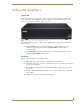
Connecting Carbon XA to a Mi-Series Audio Controller
Connect the Carbon XA Amplifier to the Mi-Series Audio Controller via the Euro-style connector
labelled “From Controller” on the rear panel of the Carbon XA.
Connecting Matrix Keypads to the Carbon XA
Connect Matrix Keypads to the Carbon XA Amplifier via the Euro-style connector labelled “To
Keypad” on the rear panel of the Carbon XA (see FIG. 1).
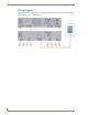
Molex Connector
FIG. 1 provides a Molex Connector Legend
Connecting Speakers
Non-SWT Speakers
Each speaker has a Red (positive) terminal and a Black (negative) terminal. Connect the appropriate wire
from the keypad to Red and Black terminals on the Left and Right speakers, as with any standard speaker
installation.
SWT Speakers
Matrix Audio SWT Speakers are different from any other speaker available on the market. They allow
you to control a single zone of audio without a keypad being installed. Therefore, some different wiring
practices must be considered for proper operation and control.
This is achieved by “daisy-chaining” from the first speaker to the second speaker. The main run of 16/4
from the controller will go directly to the first speaker in the zone.
At the controller end, the wiring is left-to-right: L D G R with the screws of the connector
facing up.
At the speaker end, refer to the labeling on speaker PCB to ensure the correct wiring.
The labelling at both ends must match or the IR control will not work (i.e.: if you used the RED wire for
the Left Audio labelled “L” at the zone output, you must use the RED wire for the pin labelled “L” on
the speaker connector).
Be sure to screw the connector down to the speaker crossover board before installing and securing in the
ceiling. This will ensure that the connector will not disconnect after installation.
A single run of 16/2 must be run from the first speaker to the second speaker.
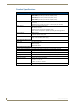
FIG. 1 Molex Connector Legend
Right +
Ground (-)
Left +
DATA
When stripping cable for use with the Euro-style connector, only strip away about ¼”
(6mm) of the insulation from each wire. The complete assembly should not have
more than 1/32” (1mm) of bare wire exposed from the bottom of the connector.