Operation/Reference Guide MXT/D-1000 10.1" Modero® X Series Tabletop Touch Panel 10.
AMX Limited Warranty and Disclaimer This Limited Warranty and Disclaimer extends only to products purchased directly from AMX or an AMX Authorized Partner which include AMX Dealers, Distributors, VIP’s or other AMX authorized entity.
AMX Software License and Warranty Agreement • LICENSE GRANT. AMX grants to Licensee the non-exclusive right to use the AMX Software in the manner described in this License. The AMX Software is licensed, not sold. This license does not grant Licensee the right to create derivative works of the AMX Software. The AMX Software consists of generally available programming and development software, product documentation, sample applications, tools and utilities, and miscellaneous technical information.
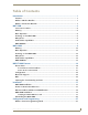
Table of Contents Table of Contents Introduction ........................................................................................................1 Features.................................................................................................................... 1 Modero X Dealer Benefits ........................................................................................ 1 Modero X Customer Benefits ...................................................................................
Table of Contents Upgrading Firmware .........................................................................................29 Upgrading Firmware via USB stick.......................................................................... 29 Upgrading from Previous Firmware ........................................................................ 30 Returning to Factory Default Firmware .................................................................. 31 Upgrading Firmware Via NetLinx Studio .................
Introduction Introduction See more and do more with the most elegant interface designed specifically for dedicated room control. The Modero X® Series Touch Panels provide several industry firsts, including a beautiful, panoramic capacitive multi-touch screen that provides users access to multiple applications with minimal navigation.
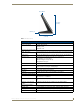
MXT-1000 MXT-1000 The MXT-1000 (FG5968-03) (FIG. 1) is ideal for boardrooms, conference rooms, or auditoriums where a panoramic control surface is needed to provide access to multiple functions simultaneously while remaining elegantly unobtrusive. In residences, it is perfect for kitchens, home theaters, or home offices where the panoramic control surface can be used to manage systems throughout the house. NFC Sensor Sleep Button 6 14/16" (174 mm) 9 14/16" (252 mm) FIG.
MXT-1000 Sleep Button 6 14/16" (74 mm) USB Ports (2) 4 14/16" (124 mm) FIG. 2 MXT-1000 side view MXT-1000 Specifications Power Requirements: PoE (Power over Ethernet), 802.3af, class 3 Power Consumption: • Full-On: 8W maximum • Standby: 3.2 W • Shutdown: 1 W Front Panel Components: NFC Transceiver: Antenna and transceiver for Near Field Communications device detection and interaction. Light Sensor: Photosensitive light detector for automatic adjustment of the panel brightness.
MXT-1000 MXT-1000 Specifications (Cont.) Touch Panel Display (Cont.): Viewing Angle: • Vertical: ± 89° • Horizontal: ± 89° Screen Resolution (W x H): 1200x800 Aspect Ratio (W x H): 16x9 Brightness: 400 cd/m2 Contrast Ratio: 1000:1 Color Depth: 264K colors Backlight Type: LED Touch Overlay: Projected Capacitive; Multi-touch support, 3 simultaneous max. Communications: Ethernet: 10/100 port, RJ-45 connector and cable.
MXT-1000 MXT-1000 Specifications (Cont.) Other AMX Equipment: • PS-POE-AT, High-Power PoE Injector (FG423-81) • PS-POE-AF-TC, POE Injector, 802.3af Compliant (FG423-83) • MXA-BT Bluetooth USB Adaptor (FG5968-19) • MXA-CLK, Modero X Series Cleaning Kit (FG5968-16) • NXA-ENET8POE, Gigabit PoE Ethernet Switch (FG2178-62) • NXA-ENET8-2POE, Gigabit Switch, 8 Port POE, 2 Port SFP (FG2178-63) MXD/T-1000 10.
MXT-1000 Connector Locations With the unit facing you, the two USB ports for peripherals are located on the rear right corner of the device (FIG. 3). The RJ45 connector for PoE, as well as a 5-pin Micro-USB port, is also located on the back of the device. USB Ports Entry for RJ45/ PoE Cable Speaker Micro-USB Port FIG. 3 MXT-1000 USB port location In addition to its speaker, the MXT-1000 also utilizes its Micro-USB port for video output from camera video and microphone output.
MXT-1000 MXT-1000-NC The MXT-1000-NC (FG5968-24) No Comm touch panel does not have camera, microphone, or NFC capability. It otherwise has all of the functionality of the MXT-1000 panel. MXD/T-1000 10.
MXD-1000 MXD-1000 The MXD-1000 10.1” Modero X Series Panoramic Wall Touch Panels (Portrait Wall Mount: FG5968-07; Landscape Wall Mount: FG5968-13) are ideal for boardrooms, conference rooms, or auditoriums where a panoramic control surface is needed to provide access to multiple functions simultaneously while remaining elegantly unobtrusive. In residences, they are perfect for kitchens, home theaters, or home offices where the panoramic control surface can be used to manage systems throughout the house.
MXD-1000 Sleep Button NFC Sensor FIG. 5 MXD-1000, Portrait Wall Mount Micro-USB Port USB Port Top RJ45 Port FIG. 6 Rear of the MXD-1000 (Portrait) MXD/T-1000 10.
MXD-1000 MXD-1000 Specifications Power Requirements: PoE (Power over Ethernet), 802.3af, class 3 Power Consumption: • Full-On: 8W maximum • Standby: 3.2 W • Shutdown: 1 W Front Panel Components: NFC Transceiver: Antenna and transceiver for Near Field Communications device detection and interaction. Light Sensor: Photosensitive light detector for automatic adjustment of the panel brightness. Motion Sensor: Proximity detector to wake the panel when it is approached. • Typical Range: 1 foot (30.
MXD-1000 MXD-1000 Specifications (Cont.) Communications (Cont.): Bluetooth: HID Profile v1.1, Keyboard/Mouse Support, requires MXA-BT Bluetooth Adaptor. Video: Streaming/File Formats: MPEG-TS for MPEG2; HTTP for MJPEG Video Conferencing (Landscape Only): External application using on-board camera and microphone through Micro-USB connection. Audio: Streaming/File Formats: Intercom: Operating Environment: WAV, MP3 Full Duplex VoIP, SIP v2.
MXD-1000 Memory The MXD-1000 comes with 512 MB of SDRAM and 4 GB of Flash memory, neither of which can be upgraded. A maximum of 2.4 GB is available to the user for projects. Basic Operation The MXD-1000 is operated using its integral touchscreen, as well as the Sleep button on the top of the device (FIG. 4). If the device has gone into its Sleep Mode, a touch of the touchscreen or of the Sleep button will reactivate it.
MXD-1000 MXD-1000-NC The MXD-1000-P-NC (FG5968-25) and MXD-1000-L-NC (FG5968-26) No Comm touch panels do not have camera, microphone, or NFC capability. These otherwise have all of the functionality of the MXD-1000 panels. MXD/T-1000 10.
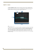
MXD/T-1000 Features MXD/T-1000 Features Picture View By connecting a USB drive via one of the device’s USB ports (FIG. 3), Picture View allows the MXT-1000 to access JPEG images on that drive and display them on the touchscreen (FIG. 7). Individual images may be accessed at any time, or the entire collection may be displayed for predetermined times. Picture View may be stopped at any time by removing the USB drive, and the MXT-1000 will return to its default display page. FIG.
MXD/T-1000 Features Pause/ Resume Stop Random/ A-Z Counter Previous image saved Next image saved Timer FIG. 8 Picture View configuration popup menu The Pause/Resume button allows the display to stop on one particular image. Press it again to resume the display procession. The Next Image Saved button returns the display to the last image uploaded by Page View. If the panel has not accessed all of the images available on a USB drive, Page View will display the last one uploaded to date. 5.
MXD/T-1000 Features Configuration The MXT-1000 and MXD-1000 are equipped with Settings Pages that allow you to set and configure various features on the panels. For more information on connecting and configuring the touch panels to a network, please refer to the Modero X Series Programming Guide, available at www.amx.com. Bluetooth Support Both the MXT-1000 and the MXD-1000 allow the use of Bluetooth keyboard and mouse combinations, using HID Profile v1.1.
Installation Installation MXT-1000 Installation Any USB peripherals (mouse, keyboard, etc.) may be connected to one of the two USB ports on the rear of the device (FIG. 9). Updates to the device’s firmware are also made via the USB ports. The 5-pin Micro-USB port is used exclusively for camera video and microphone output only. Entry for RJ45/ PoE Cable USB Ports Speaker Micro-USB Port FIG.
Installation Ethernet Cable Installation and Modification In installations where you wish to conceal the Ethernet cable, a hole at least 1.00” (2.54 cm) in diameter is required in the surface to allow passage of the female RJ45 connector (FIG. 11). If using a smaller hole is unavoidable, you will need to disconnect the Ethernet cable (ECA5968-05) from the device. The minimum diameter hole through which the Ethernet cable may pass is 0.50" (1.27 cm). MXT-1000 Ethernet Cable Clamp Connector FIG.
Installation MXD-1000 Installation The MXD-1000 may be installed directly into a solid surface environment, using either solid surface screws or the included locking tabs for different mounting options. Once installed, the MXD-1000 is contained within a clear outer housing known as the back box (FIG. 12). This back box is removed when installing the device into a wall or into a Rough-In Box. Locking tabs Locking tabs FIG.
Installation Back box knockouts Locking tab MXD-1000 (front) Back box FIG. 13 Side view of MXD-1000 (Landscape) MXD-1000 (front) Sleep Button Back box knockouts Locking tabs FIG. 14 Side view of MXD-1000 (Portrait) In order to guarantee a stable installation of the MXD-1000, the thickness of the wall material must be a minimum of .50 inches (1.27cm) and a maximum of .875 inches (2.22cm). The mounting surface should also be smooth and flat.
Installation 1. Prepare the area by removing any screws or nails from the drywall before beginning the cutout process. 2. For best results, use the MXD-1000 Installation Template (68-5968-03) to ensure proper placement (FIG. 15). The template is marked on one side with directions for both landscape and portrait installations to ensure that the touch panel and back box are properly aligned. 9 7/8" (25.08cm) 8 3/4" (22.23cm) 6 3/4" (17.15cm) 5 1/2" (13.97 m) FIG.
Installation Mounting Surface Locking Tabs #4 Screws Knockouts Back Box FIG. 16 MXD-1000 Back Box Installation (Portrait) 4. Thread the incoming Ethernet and Micro-USB wiring (if Micro-USB access is desired) from their terminal locations through the surface opening (FIG. 16 ). Leave enough slack in the wiring to accommodate any re-positioning of the panel. 5. Remove the back box knockouts (FIG. 16) and thread the incoming wiring through the knockout holes.
Installation 10. Insert each connector into its corresponding location along the back of the device (FIG. 17). To reach the RJ45 connector, gently pull it from beneath the electronics cover (FIG. 18). Attach the Ethernet cable and gently push the connection back under the cover. Micro-USB Port USB Port Top RJ45 cable clip RJ45 Port FIG. 17 Rear of the MXD-1000 (Portrait) Top RJ45 Cable Clip RJ45 Port FIG. 18 Rear of the MXD-1000 (detail of the RJ45 connection) 11.
Installation 12. Latch the panel onto the top hooks on the back box and push it down (Landscape) onto the bottom snaps or on the left side and push it to the right (Portrait) (FIG. 19). Press gently but firmly on the ends until the snaps “click” to lock it down MXD-1000 Landscape) Latch Hooks Back Box Mounting Surface Snaps FIG.
Installation Uninstalling the MXD-1000 The MXD-1000 is held in place to the back box via latch hooks and clips on the back box (FIG. 19), securing it to the mounting surface. In certain circumstances, such as firmware updates or other maintenance that requires accessing the device’s USB or Micro-USB ports, the device may need to be removed from the back box.
Installation 26 MXD/T-1000 10.
Configuration and Programming Configuration and Programming Programming the MXT-1000 and MXD-1000 require the use of the latest versions of NetLinx Studio and TPDesign 4, both available at www.amx.com. Modero X Series Programming Guide Information on Settings pages, panel configuration, and programming is included in the Modero X Series Programming Guide, available at www.amx.com. MXD/T-1000 10.
Configuration and Programming 28 MXD/T-1000 10.
Upgrading Firmware Upgrading Firmware Programming the MXT-1000 and MXD-1000 require the use of the latest versions of NetLinx Studio and TPDesign 4, both available from www.amx.com. Upgrading Firmware via USB stick Firmware and TPDesign 4 file downloads may be made via USB stick. When looking at the device from the front, the MXT-1000 has two USB ports on the rear right of the device (FIG. 3). To upgrade the firmware on the MXT-1000 and MXD-1000 to the latest version: 1.
Upgrading Firmware 8. The Confirmation Dialog box (FIG. 24) will ask “Are you sure you want to install the following firmware?” The option to choose Yes will be enabled after five seconds. Press Yes to load the firmware listed, and No to return to the Firmware Installation popup window. FIG. 23 New Firmware installation confirmation dialog box 9. The device will now upload the new firmware and then reboot.
Upgrading Firmware Returning to Factory Default Firmware The MXT-1000 and MXD-1000 allow the option to return the device to its original factory default firmware, which may be necessary in certain situations. To return the device to its factory default firmware: 1. From the Settings page, select the Configuration page. 2. From the Configuration page, select Admin. 3. From the Admin Configuration page, select Install Firmware. 4. In the Firmware Installation page, select Factory. 5.
Upgrading Firmware Upgrading Firmware Via NetLinx Studio The MXT-1000 and MXD-1000 use an Ethernet connection for programming, firmware updates, and touch panel file transfer via NetLinx Studio. If you have access to the panel’s network, you may transfer files directly to the panel through NetLinx Studio Firmware upgrades cannot be made through an Ethernet-connected PC to the touch panel, unless that PC is connected to the panel’s network.
Upgrading Firmware 5. Click the Edit Settings button on the Communications Settings dialog to open the Virtual NetLinx Master Settings dialog (FIG. 28). FIG. 28 Virtual NetLinx Master Settings 6. Within this dialog, enter the Master System number. The default is 1. 7. In the Available Connections section, click on the IP address for the touch panel to select it. 8. In the Virtual NetLinx Master Settings dialog box, click OK to close the box. 9.
Upgrading Firmware Viewing devices on the Virtual System 1. After the Communication Verification dialog window verifies active communication between the Virtual Master and the panel, click the OnLine Tree tab in the Workspace window (FIG. 29) to view the devices on the Virtual System. The default System value is 1. 2. Right-click on the System entry (FIG. 29) and select Refresh System to re-populate the list. Verify the panel appears in the OnLine Tree tab of the Workspace window.
Upgrading Firmware 3. Select Tools > Firmware Transfers > Send to NetLinx Device from the main menu to open the Send to NetLinx Device dialog (FIG. 30). Verify that the panel’s System and Device number values match those values listed within the System folder in the OnLine Tree tab of the Workspace window. FIG. 30 Send to NetLinx Device dialog window 4. Select the appropriate Kit file from within the Browse for Folder window (FIG. 31). FIG. 31 Browse for Folder window 5.
Upgrading Firmware 36 MXD/T-1000 10.
Appendix: Troubleshooting Appendix: Troubleshooting Overview This section describes the solutions to possible hardware/firmware issues that could arise during the common operation of a Modero X touch panel. Panel Doesn’t Respond To Touches Symptom: The device either does not respond to touches on the touch screen or does not register the touch as being in the correct area of the screen. If the screen is off: The device may be in Display Sleep Mode. Press and hold the Sleep button to wake up the panel.
Appendix: Troubleshooting 38 MXD/T-1000 10.
Appendix - Troubleshooting MXD/T-1000 10.
AMX. All rights reserved. AMX and the AMX logo are registered trademarks of AMX. AMX reserves the right to alter specifications without notice at any time. ©2012 7/2012 It’s Your World - Take Control™ 3000 RESEARCH DRIVE, RICHARDSON, TX 75082 USA • 800.222.0193 • 469.624.8000 • 469-624-7153 fax • 800.932.6993 technical support • www.amx.