Instruction Manual Precis SD Distribution Matrix Matrix Switchers Release: 10/20/2008 (Firmware v1.4.
AMX Limited Warranty and Disclaimer All products returned to AMX require a Return Material Authorization (RMA) number. The RMA number is obtained from the AMX RMA Department. The RMA number must be clearly marked on the outside of each box. The RMA is valid for a 30-day period. After the 30-day period the RMA will be cancelled. Any shipments received not consistent with the RMA, or after the RMA is cancelled, will be refused. AMX is not responsible for products returned without a valid RMA number.
Software License and Warranty Agreement • LICENSE GRANT. AMX grants to Licensee the non-exclusive right to use the AMX Software in the manner described in this License. The AMX Software is licensed, not sold. This license does not grant Licensee the right to create derivative works of the AMX Software. The AMX Software consists of generally available programming and development software, product documentation, sample applications, tools and utilities, and miscellaneous technical information.
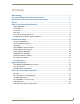
Contents Contents ESD Warning .......................................................................................................1 Important Safety Information & Instructions .......................................................2 Information et directives de sécurité importantes...............................................3 Notices ................................................................................................................4 Overview & General Specifications .....................
Contents Appendix A – Managing Configuration Files .................................................... 45 Overview ............................................................................................................................... 45 Installing & Launching XNConnect......................................................................................... 46 Discovering a System.............................................................................................................
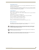
ESD Warning ESD Warning To avoid ESD (Electrostatic Discharge) damage to sensitive components, make sure you are properly grounded before touching any internal materials. When working with any equipment manufactured with electronic devices, proper ESD grounding procedures must be followed to ensure people, products, and tools are as free of static charges as possible. Grounding straps, conductive smocks, and conductive work mats are specifically designed for this purpose.
Important Safety Information & Instructions Important Safety Information & Instructions When using and installing your AMX AutoPatch product, adhere to the following basic safety precautions. For more information about operating, installing, or servicing your AMX AutoPatch product, see your product documentation. Read and understand all instructions before using and installing AMX AutoPatch products. Use the correct voltage range for your AMX AutoPatch product.
Information et directives de sécurité importantes Information et directives de sécurité importantes Veuillez vous conformer aux directives de sécurité ci-dessous lorsque vous installez et utilisez votre appareil AMX AutoPatch. Pour de plus amples renseignements au sujet de l’installation, du fonctionnement ou de la réparation de votre appareil AMX AutoPatch, veuillez consulter la documentation accompagnant l’appareil.
Notices Notices Copyright Notice AMX© 2008 (Rev B), all rights reserved. No part of this publication may be reproduced, stored in a retrieval system, or transmitted, in any form or by any means, electronic, mechanical, photocopying, recording, or otherwise, without the prior written permission of AMX.
Notices Lithium Batteries Notice Switzerland requires the following notice for products equipped with lithium batteries. This notice is not applicable for all AMX equipment. Upon shipment of the products to Switzerland, the requirements of the most up-to-date Swiss Ordinance Annex 4.10 of SR 814.013 will be met by providing the necessary documents and annual reports relative to the disposal of the batteries to the Swiss Authorities. Trademark Notices AMX®, AutoPatch®, and NetLinx® are trademarks of AMX.
Notices 6 Precis SD Instruction Manual
Overview & General Specifications Overview & General Specifications Applicability Notice The information in this manual applies to Precis SD (Slam Dunk) systems. For other types of Precis systems, see the Precis Instruction Manual.
Overview & General Specifications Precis SD Control Features Precis SD systems support three different protocols: BCS* (Basic Control Structure), XNNet, and TCP/IP. Several different control options are available. Multiple control methods can be used on the same system. Simple Touch X/Y Control Panel featuring backlit buttons AMX control devices (for specific control programming information, contact your AMX representative) APControl 3.
Overview & General Specifications Rear View The enclosure’s appearance, as viewed from the rear, (FIG. 2) will vary depending on the configuration. CPU/Control hardware Input connectors Serial number Output connectors Power receptacle FIG. 2 Precis SD 12x8 enclosure rear view Rear View Components CPU/Control hardware Power receptacle and specifications Serial number Input/output connectors The following sections briefly introduce the hardware on the rear of an enclosure.
Overview & General Specifications Power Receptacle & Specifications The universal power receptacle is in the lower left hand corner on the rear of the enclosure (FIG. 4). Maximum power specifications are on the power receptacle. The power receptacle will accept all major international standard power sources. (Standard US power cords are provided for installations within the US.) The fuse is internal and is not field serviceable.
Overview & General Specifications Precis SD General Specifications General Specifications Parameter Value Approvals CE, ETL, cETL Humidity 0 to 90% non-condensing Operational Temperature 32°F to 110° F (0°C to 43° C) MTBF 87,600 hours AC Power* 100 VAC to 240 VAC single phase, 50 Hz to 60 Hz Power Consumption (max.) 80 Watts per enclosure Power Consumption (typical) 57 Watts per enclosure Thermal Dissipation (max.) 273 BTU/hr. Thermal Dissipation (typical) 194 BTU/hr.
Overview & General Specifications Configuration Information & Control Options The factory configuration of the Precis SD is constructed internally by the CPU upon initial boot up of the system and contains routing and control information for that particular model of (for model numbers and descriptions, see the “Applicability Notice” on page 7). Configuration Information As shipped from the factory, the Precis SD supports Device Discovery (firmware v1.4.1 required).
Overview & General Specifications BCS Serial Control Protocol The Precis SD can be controlled with an external serial controller that sends and receives ASCII characters via the CONTROL port. AMX AutoPatch has developed a command language, BCS (Basic Control Structure) protocol, for programming control operations and for diagnostic purposes. BCS commands can be entered into a terminal emulation program (such as, HyperTerminal) running on a PC.
Overview & General Specifications 14 Precis SD Instruction Manual
Installation & Setup Installation & Setup Site Recommendations When placing the enclosure, follow the recommendations and precautions in this chapter to reduce potential installation and operation hazards. Environment Choose a clean, dust free, (preferably) air-conditioned location. Avoid areas with direct sunlight, heat sources, or high levels of EMI (Electromagnetic Interference). To make control panel operations easier, mount the enclosure with the control panel in the rack at eye level.
Installation & Setup Circuit Overloading When connecting the equipment to the supply circuits, be aware of the effect that overloading the circuits might have on over-current protection and supply wiring. Reliable Earthing (Grounding) Reliable earthing of rack-mounted equipment should be maintained. If not using a direct connection to the branch circuit (e.g., plugging into a power strip), pay particular attention to supply connections.
Installation & Setup Rack Installation & System Setup The Precis SD Distribution Matrix enclosure can be mounted in a standard EIA 19 in. (48.26 cm) rack. Rack installation ears are included, and directions for attaching the rack ears are included in the rack installation instructions (page 18). Important: The system requires at least one empty rack unit above and below the enclosure to allow adequate airflow; three empty rack units are recommended.
Installation & Setup Installation Procedure A flow chart showing the installation sequence is in FIG. 5. The procedure following provides general steps with references to detailed information found later in this manual. FIG. 5 Installation procedure Caution: To prevent overheating and airflow restriction, avoid placing high heat producing equipment directly above or below the enclosure. The system requires a minimum of one empty rack unit above and below (three empty rack units are recommended).
Installation & Setup 4. Attach only the first two source and destination devices; see “Attaching Inputs & Outputs” on page 24. Do not apply power to the devices until after the Precis SD has power (Step 5). 5. Apply power to the system according to the power-up procedure; see “Applying Power & Startup” on page 27. Note: We recommend using surge protectors and/or AC line conditioners. 6. Execute a test switch to ensure the system is working properly; see “Executing a Test Switch” on page 29. 7.
Installation & Setup Attaching External Controllers The Precis SD can be controlled by attaching an external control device that uses one of the communication protocols listed below: BCS (Serial) – ASCII sent over a null modem serial cable via the CONTROL port XNNet – AMX AutoPatch protocol via all ports (including serial); AMX AutoPatch control and accessory devices usually connect via the REMOTE port Important: The ENC LINK (Ethernet RJ-45) connector on the CPU is not a TCP/IP interface and is used for l
Installation & Setup Attaching Serial Controllers An external serial controller is any device that can send and receive ASCII code over an RS-232 (null modem) serial cable attached to the CONTROL port on the enclosure’s CPU. PCs are common serial controllers. Once a PC is attached to the Precis SD, the system can be controlled by running APControl software on the attached PC (see the AMX AutoPatch CD). The system can also be controlled by entering BCS commands into a terminal emulation program (e.g.
Installation & Setup 2. Plug one end of the null modem serial cable into the CONTROL port on the enclosure (FIG. 9). FIG. 9 Attach null modem serial cable to CONTROL port 3. Plug the other end of the serial cable into the serial port on the serial controller/device. 4. Open the serial communication software on the PC and set the PC’s port settings to match the Precis SD default settings (see table to the right).
Installation & Setup Attaching External XNNet Controllers An XNNet device is any device that sends and receives XNNet protocol over the REMOTE port. AMX AutoPatch XNNet control devices include remote control panels, Single Bus Controllers (SBCs), and Preset SBCs. The instructions below are for attaching a device to the REMOTE port, found on the CPU. For specific product information, see the individual device’s documentation.
Installation & Setup Attaching Inputs & Outputs Input and output connectors are the attachment points for source and destination devices that connect to the system. Viewed from the rear of a Precis SD enclosure, the inputs (for sources) are on the left side of the enclosure, and the outputs (for destinations) are on the right side. The number and type of connectors depend on the signal type and system configuration. Input and output connectors are numbered separately.
Installation & Setup Cabling Video Connectors The video connectors are color coded; the white BNC connectors are inputs and the black BNC connectors are outputs. Tip: Using lacer bars or some other type of cable management system lessens the strain from cable weight on the connectors and makes servicing the enclosures easier. For RGBHV signals, you need to attach corresponding input and output connectors on five connectors to route the entire signal. FIG.
Installation & Setup Wiring Audio Connectors The stereo audio connectors for the Precis SD are pluggable 5-position terminal block that can be wired for balanced (differential) or unbalanced (single-ended) audio (FIG. 14). Wiring Sources & Destinations Source and destination devices require either balanced (differential) or unbalanced (single-ended) connections. FIG. 13 illustrates options for wiring between sources and input connectors and between output connectors and the destinations.
Installation & Setup Applying Power & Startup The enclosure’s universal power receptacles will accept all major international standard power sources. Standard US power cords are provided for installations within the US. Maximum power specifications are on the power receptacle (also listed on page 11). Always use an earth-grounded power cord / system with a Precis SD. The source electrical outlet should be installed near the Precis SD, easily accessible, and properly grounded.
Installation & Setup Serial Control Device Startup If you have not already done so, attach the serial control device to the CONTROL port on the enclosure (see page 20) and open the control program. AMX Control Devices The Precis SD is compatible with a number of AMX control devices. For specific control programming information, contact your AMX representative. APControl 3.0 If you are using APControl 3.0, install and open the program. Follow the directions in the setup wizard.
Installation & Setup Executing a Test Switch Execute a test switch to verify the system is working properly before attaching all inputs and outputs. Aside from having signal cables (and a controller if applicable) attached, the system is ready to execute switches when it ships from the factory. Important: The Precis SD ships from the factory with a default switch of Input 1 to all outputs. Before executing the test switch, you will need to disconnect the factory default switch.
Installation & Setup Control Panel All Level Key Input Keys Output Keys Cancel Key FIG. 17 Precis SD 12x8 control panel To disconnect the factory default switch using the control panel: 1. Press the Cancel Key to place the panel in Switch mode. All the lights on the control panel turn off. The control panel is in Switch mode. 2. Press the All Level Key. The All Level Key illuminates. 3. Press Input Key 1. Input Key 1 flashes. After a moment, all the Output Keys illuminate. 4.
Installation & Setup BCS Commands To enter BCS commands, the system must be attached to a serial control device (see “Attaching External Controllers,” on page 20) running a terminal emulation program such as Windows® HyperTerminal. The settings on the PC serial communication software and the enclosure must correspond to each other. For settings information, see the table on page 22.
Installation & Setup Technical Support Before contacting technical support with a question, please consult this manual. If you still have questions, contact your AMX representative or technical support. Have your system’s serial number ready. The system’s serial number is normally located in two places on the enclosure; on the left rear and on the left side (near the power receptacle). We recommend recording your system’s serial number in an easily accessible location.
Signal Specifications Signal Specifications This chapter contains the specifications for the video and audio signals routed by the Precis SD system. For information on cabling and wiring video and audio connectors, see “Attaching Inputs & Outputs” on page 24. Ultra-Wideband (500 MHz) Specifications Ultra-Wideband (500 MHz) Signal Specifications Parameter Conditions Frequency Response Crosstalk (adjacent channel) Value ±3 dB to 500 MHz or better f = 5 MHz <-60 dB Signal to Noise Ratio (SNR) Vin = 0.
Signal Specifications Standard Audio Specifications Standard Audio Signal Specifications Parameter Conditions Value Frequency Response 20 Hz to 20 kHz THD + Noise 20 Hz to 20 kHz, Vin = -10 dBu to +20 dBu <0.1% Crosstalk f = 1 kHz, Vin = +14 dBu <-90 dB Signal to Noise Ratio (SNR) 20 Hz to 20 kHz, Vin = +10 dBu >80 dB Input Level (max.) Balanced +27 dBu Input Impedance 18 kohms Input Gain Adjustment Range Control panel or serial control adjustment Output Level (max.
Precis SD Control Panel Operation Precis SD Control Panel Operation Overview All Precis SD systems have an integral Precis X/Y Control Panel for controlling the system’s switches and system attributes. The control panel can also be used for system verification, redundant control, and troubleshooting. FIG. 18 illustrates a Precis SD 12x8 with digital volume control. Other models may vary slightly in appearance. FIG.
Precis SD Control Panel Operation Control Keys Macro Key or Up Arrow Key (for audio) Lock Key or Down Arrow Key (for audio) Level Keys Input Keys Output Keys Cancel Key Status Key or Volume Adjust Key (for audio) FIG.
Precis SD Control Panel Operation Executing & Disconnecting Switches A switch is an active connection between an input (source) device and one or more output (destination) devices. The signals routed in a switching operation are individual signals or groups of individual signals coming through the connectors on the rear of an enclosure. You can execute switches from the Control Panel using the steps below or by executing a local preset / macro (see page 40).
Precis SD Control Panel Operation Note: Only one input signal can be routed to any given output. To execute a switch selecting output (destination) first: 1. Press the Cancel Key. All the lights on the control panel turn off. The control panel is in Switch mode. 2. Press a Level Key to select a level (can be omitted when switching on the default level). The Level Key illuminates. 3. Press an Output Key to select an output.
Precis SD Control Panel Operation Verifying Signal Status Signal status can be verified to confirm that a switch has executed properly or to confirm correct routing to multiple outputs (destinations) without accidently executing or disconnecting switches. Input status and output status both function on the Precis SD Control Panel. An output can only be connected to one input (source); therefore, verifying the status of an output will illuminate only the one input it is currently connected to.
Precis SD Control Panel Operation Executing Macros (Local Presets) Note: For Precis SD systems, the terms “macro” and “local preset” are interchangeable. A macro (local preset) is a predetermined set of switches on a particular level (virtual matrix) that are routed simultaneously. A Precis SD can execute as many macros per level as there are Input and Output Keys.
Precis SD Control Panel Operation Adjusting Audio Some Precis SD systems offer optional volume control and digital input gain adjustment features. If your system supports audio adjustments, output volume or digital input gain can be adjusted using either the control panel or BCS commands sent through a serial controller. (For information on audio adjustment using BCS commands, see the BCS Protocol Instruction Manual.
Precis SD Control Panel Operation Adjusting Digital Input Gain If your system has digital input gain control, adjustments (within the gain range for the specific audio inputs) can be made at any time during normal operation. When audio is adjusted for a device on one level, the adjustment remains in effect for that device on all levels switching audio signals. Caution: We strongly recommend that digital input gain adjustments be made only by a qualified dealer or installer.
Precis SD Control Panel Operation Locking & Unlocking the Control Panel The Precis SD Control Panel can be locked by pressing a sequence of Level Keys. Locking the panel prohibits access to the system and can prevent accidental switching. The password can be any combination of the first five Level Keys. The factory default password is the first five Level Keys, going from left to right. The password can be changed using XNConnect (see page 51).
Precis SD Control Panel Operation 44 Precis SD Instruction Manual
Appendix A – Managing Configuration Files Appendix A – Managing Configuration Files Applicability Notice This appendix applies to XNConnect version 2.8.0. (XNConnect’s version number is found under its Help menu.) Version 2.8.0 supports Device Discovery (firmware v1.4.1 is required).
Appendix A – Managing Configuration Files Installing & Launching XNConnect Use XNConnect software only if you need to customize or change the configuration information from the original specification. Even if XNConnect is already on your PC, install the newest version that shipped on the CD that shipped with your system. We strongly recommend uninstalling the old version of XNConnect before installing a new version.
Appendix A – Managing Configuration Files 4. Select XNConnect. The XNConnect program opens. Getting Started dialog box When XNConnect is open, you can do either of the following: Discover the system (recommended); see below. Open an .xcl file that is compatible with the system (located on the AMX AutoPatch CD); see page 48.
Appendix A – Managing Configuration Files Opening an .xcl Configuration File The process of modifying an .xcl configuration file starts by opening it with XNConnect. After the modifications are complete, the new configuration information must be loaded onto the system to implement the changes. Important: Even if XNConnect is already on your PC, install the newest version that shipped on the same CD as the .xcl configuration file.
Appendix A – Managing Configuration Files Navigating the Interface XNConnect displays configuration information in two panes. The graphics are located in the left pane, and the properties of the currently selected graphic are in the right pane. At the top of the left pane are two tabs, Hardware and Virtual Matrices, for accessing the Hardware and Virtual Matrix (level) views (see below).
Appendix A – Managing Configuration Files Modifying an .xcl Configuration File Modifying an .xcl configuration file with XNConnect involves entering information in a field or in a series of dialog boxes. A brief look at the contents in the Help file provides a quick overview of the possible modifications. This section provides instructions for three common tasks: modifying channel names, configuring local presets, and setting the control panel password.
Appendix A – Managing Configuration Files Setting the Control Panel Password Important: The control panel password can be set without loading the entire .xcl configuration file to the system, thereby retaining the factory configuration with the Device Discovery feature. For Precis SD control panels, the numbers in the password correspond to the Level Keys (in order from left to right, the level Keys represent the numbers “0” to “7”).
Appendix A – Managing Configuration Files Creating Local Presets (Macros) A local preset is a predetermined collection of switches on the same virtual matrix (level) to be routed simultaneously. Executing a local preset affects only those inputs and outputs specified, not the whole system. Local presets are defined using XNConnect and can be executed using the control panel or using BCS commands entered as part of a macro in APControl 3.0 or APWeb or entered in a terminal emulation program.
Appendix A – Managing Configuration Files 7. For the first switch, click the source channel (input) and one or more destination channels (outputs). Select multiple destination channels by holding down the Control key while selecting the channels. The Assignment column shows three switches that will be executed as part of Preset 2: Input 2 to Output 5 Input 3 to Output 6 Input 7 to Output 8 The Disconnected Channels box shows that Output 1 will be disconnected as part of Preset 2. 8.
Appendix A – Managing Configuration Files Loading an .xcl Configuration File Once modifications have been made to the .xcl configuration file, the file must be loaded onto the system’s CPU for the changes to be implemented. When loading the.xcl configuration file, the matrix switcher must not be actively switching. You may want to disconnect any external controllers to ensure that no switches are executed during the loading of the file.
Appendix B – Programmer’s Interface for System Diagnostics Appendix B – Programmer’s Interface for System Diagnostics System Component Information The Precis SD displays system information in its splash screen* for diagnostic purposes. The information indicates the current status and well-being of the system components.
Appendix B – Programmer’s Interface for System Diagnostics Verbosity Settings The verbosity (v) settings (v0, v1, v2, v3) correspond to the level of detail that will be displayed, with v0 being the lowest level of detail and v3 being the highest level. Component Settings Detailed information for a single system component can be specified by using its identity (i) number setting (i0 through i5) in the following table.
Appendix B – Programmer’s Interface for System Diagnostics Splash Screen Examples Following are four examples of splash screen information that could be displayed when different verbosity/component settings are specified. Depending on the amount of detail provided, you may need to scroll to see the entire display. Use the first example to check the host software (IOS) version and the hardware driver (appcode) version. ~scrv1i1! [1:Enclosure] AutoPatch Precis-500 [host software] v3.0.
Appendix B – Programmer’s Interface for System Diagnostics ~scrv3i4! [4:Hardware Boards] detected [io boards] count = 5 [board 1] 40d5 [board 2] 40d5 [board 3] 40d5 [board 4] 40fc [board 5] 4180 FIG. 28 Display for v3i4 (verbosity 3, component 4) ~scrv3i5! [5:VM Configuration] count = 3 [VM 0] ‘RGBHVA2’ 12x4x5 [VM 1] ‘RGBHV’ 12x4x4 [VM 2] ‘A2’ 12x4x1 [VM 0 master] 0x0 0 0 1 (self) [VM 1 master] 0x0 0 0 1 (self) [VM 2 master] 0x0 0 0 1 (self) FIG.
AMX. All rights reserved. AMX and the AMX logo are registered trademarks of AMX. AMX reserves the right to alter specifications without notice at any time. ©2008 10/08 It’s Your World - Take Control™ 3000 RESEARCH DRIVE, RICHARDSON, TX 75082 USA • 800.222.0193 • 469.624.8000 • 469-624-7153 fax • 800.932.6993 technical support • www.amx.