
Corporation Dual Zero Cross Module Installation Sheet
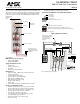
Table Of Contents
Installation Sheet
RDM-2ZC Dual Zero Cross Module
2400 W
The RDM-2ZC Dual Zero Cross Module is a dual 2400 W zero-cross relay
built for long term, reliable switching of electronic fluorescent ballasts, elec-
tronic transformers and incandescent lamps. It is designed for use with the
RDA series of enclosures, in an AMX Lighting™ modular digital dimming
system. The module's 120, 240, and 277 VAC ratings are CE, UL, and C-
UL approved.
RDM-2ZC UL and C-UL Ratings
• 120-277 VAC, 2400 W
• 240/277 VAC, 2400 W
Suggested Switched Loads
• Incandescent
• Electronic transformers
• HID ballast
• Electronic and magnetic ballast
Specifications
• Dimensions (HW): 10.00" x 2.75" (25.40 cm x 6.99 cm)
• Non-phase dependant
• Use wires rated at 75°C (167°F)
• Torque terminals to 7 in-lbs. (0.8 N/M)
• Max. wire size: 10 AWG (4 mm²)
• Wire stripping length: 0.28" (7 mm)
• Weight: 2.0 lbs. (0.91 kg)
• BTU/hr: 300
• Control current: 45 mA per relay (90 mA total) @ 12 VDC
Caution: Pre-Installation Notes
• All Class 1 wiring must be connected to proper terminals.
• All control wiring must be connected to proper terminals.
• Disconnect power while installing or connecting the unit.
• Keep top and bottom air vents clear at all times.
• Test loads for shorts before connecting.
• Use low voltage wires with a 300 volt rating or greater.
• Use field installed copper conductors.
• All electrical ratings are for continuous duty.
• For indoor use only.
• This module may require extra power from the AXlink connection or an
external power supply connected to the control card.
Connecting the RDM-2ZC to the AMX Lighting Master
Lighting Application Drawing
FIG. 1 RDM-2ZC
Low-voltage control
wiring: 4-pin connector
to AMX Lighting master
controller
Zero cross relay A
Zero cross relay B
Line in (hot)
Load out
High-voltage
connections
Mounting
points
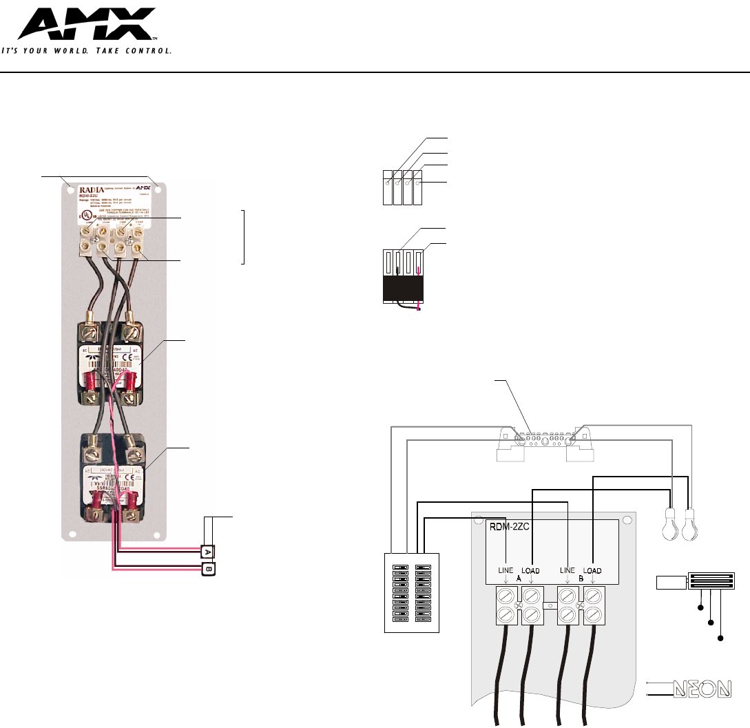
FIG. 2 RDM-2ZC connections
FIG. 3 RDM-2ZC wiring configuration
Pin 4 (GND)
Pin 3 (RLY)
Pin 2 (DIM)
Pin 1 (+12 V)
3 (-)
1 (+)
RDM-2ZC 4-pin module connector
4-pin plug from RDM series module
NOTE: The 4-pin plugs from the module connector to
the 4-pin connector on the master (black plug cover facing up).
Ballast
Circuit breaker
panel
Neon lights
(cold-cathode, on/off)
Neutral
Load
All neutrals are common
to the Neutral block in the
enclosure. Provide a
separate neutral for
each load.
(B) Load
(B) Line in (HOT)
Load
Neutral
Fluorescent Ballast
(A) Line in (HOT)
(A) Load
Safety ground