
Installation guide

For full warranty information, refer to the AMX Instruction Manual(s) associated with your Product(s).
2/13
©2013 AMX. All rights reserved. AMX and the AMX logo are registered trademarks of AMX.
AMX reserves the right to alter specifications without notice at any time.
3000 RESEARCH DRIVE, RICHARDSON, TX 75082 • 800.222.0193 • fax 469.624.7153 • technical support 800.932.6993 • www.amx.com
93-1090-170 REV: A
Preliminary Steps
Before placing the PDXL-2:
• Ensure that AC power is applied to the PDXL-2, using an operational ground
connection.
• Connect the incoming DXLink twisted pair connection to the Data port and connect the
twisted pair connection for the DXLink device to be powered to the Power port.
• Do not cover the device or block the airflow to the device with any foreign objects.
Keep the PDXL-2 away from excessive heat and humidity and free from vibration and
dust.
• Ensure that the cable length from the originating DXLink source to the final DXLink
destination does not exceed 328 feet (100 meters). The device is not a repeater and
does not amplify the DXLink data signal.
• The PDXL-2 does not have a power switch. Simply plug the device into an AC power
source.
Installing the PDXL-2
Perform the following steps to install the PDXL-2:
1. Connect the PDXL-2 to an AC outlet (100-240VAC) using an appropriate power cord.
2. Connect the DATA & POWER port to a DXLink Transmitter, Receiver, or Wallplate via
the appropriate twisted pair cable.
3. Use an additional twisted pair cable to connect the DATA port to a separate DXLink
Transmitter, Receiver, or Wallplate.
Note: If connecting both DATA & POWER ports to separate devices, use the provided
twisted pair cable to connect the two DATA ports together. Connecting the DATA ports is not
necessary if you are only connecting one DATA & POWER port to another device.
4. Connect the PDXL-2 to the I/O port on your Master so you can power off connected
devices. This step is optional.
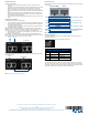
FIG. 2 displays an example configuration when using only one DATA & POWER port to
power a device. In this example, the RX is powered by the PDXL-2 while the TX is powered
by a local power supply, so a power line to the TX is not needed.
FIG. 2 Wiring using one DATA & POWER port
FIG. 3 displays an example configuration when using both DATA & POWER ports to power
two separate devices:
FIG. 3 Wiring using both DATA & POWER ports
Pin Connections
FIG. 4 describes the PDXL-2 pin-out connections for the IN and OUT Ports on the front panel
of the device.
FIG. 4 PDXL-2 pin-out connections
Relay Port Wiring
Connecting the PDXL-2 to the I/O port on your Master enables you to power off devices
connected to the PDXL-2.
FIG. 5 displays the relay port on the rear panel of the PDXL-2:
FIG. 5 Relay Port
Powering Off Connected Devices
The relay port on the PDXL-2 is set to ON by default. To set the relay port on the PDXL-2 to
OFF, you must connect the relay port to an I/O port on a Master and set the corresponding
I/O channel on the Master to ON. Consult the NetLinx Integrated Controllers WebConsole &
Programming Guide for more information on channels and commands.
To R X
To T X
(not used)
To RX
To Wallplate
twisted pair cable
Relay Port Wiring Specifications
Pin Signal Function
1 GND Signal GND
2 Relay Port 2 Input/Output
3 Relay Port 1 Input/Output
4 12 VDC PWR
Pins 1/2 (DATA only)
Pins 3/6 (DATA only)
Pins 4/5 (DATA + PWR)
Pins 7/8 (DATA + PWR)
= TransformerNote:
DATA
DATA
DATA
DATA
POWER (+)
POWER (-)
DATA & POWER DATA