
Instruction manual

Appendix D – Cable Details and Pinout Info
116
Instruction Manual – DXLink™ Fiber Transmitters and Receivers, Duplex
Appendix D – Cable Details and Pinout Info
Overview
The DXLink Fiber Transmitters and Receivers each have an HDMI connector. The Transmitters also have an HDMI
output connector on the front for sending the video signal directly from the source to a local destination device. This
connection supports the same input resolutions contained in the first table in “Appendix E - Supported Input
Resolutions” (see page 119).
Important: System configurations will vary, necessitating different cable requirements for each system.
Cables not available through AMX should come from a trusted cable supplier.
Note: When cabling video through either the HDMI port or HD-15 port, installers should be aware of how
cabling will affect audio signals. For information on audio precedence, see “Audio Type Precedence” on
page 42.
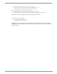
HDMI Connector Cable Pinout
HDMI connectors are found on all DXLink Fiber units. These connectors are used to pass HDMI or DVI-D signals
(using a DVI-to-HDMI cable) from a source device to a DXLink Fiber Transmitter or from a DXLink Fiber Receiver to
a destination device. They are also used to provide an HDMI signal out from the Transmitters to a local destination
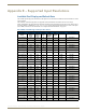
device. The following table provides cable pinout details for HDMI connections.
FIG. 27 Pinout table and HDMI receptacle pins on DXLink Fiber unit
Note: DVI-to-HDMI cables may be required for particular
system needs (see page 118).
HDMI Connector Cable Pinout
Pin Signal Assignment
1TMDS Data 2+
2 TMDS Data 2 Shield
3TMDS Data 2-
4TMDS Data 1+
5 TMDS Data 1 Shield
6TMDS Data 1-
7TMDS Data 0+
8 TMDS Data 0 Shield
9TMDS Data 0-
10 TMDS Clock+
11 TMDS Clock Shield
12 TMDS Clock-
13 CEC
14 Utility
15 SCL
16 SDA
17 DDC/CEC Ground
18 +5 V Power (max. 55 mA)
19 Hot Plug Detect