
Instruction manual

Overview DXLink Fiber, Duplex
26
Instruction Manual – DXLink™ Fiber Transmitters and Receivers, Duplex
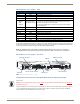
Quick Reference Tables for Modes
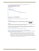
The DXLink Fiber Transmitters and Receivers, Duplex ship with either a single mode or multimode fiber optic
transceiver, which determines the maximum length of the fiber optic cable that can be used (see “Product Notes” on
page 13).
The Transmitters and Receivers also have modes that can be determined during setup to: (1) handle the system
architecture, (2) accommodate networking needs, and (3) process video signals. The modes are listed in the following
three tables and are supported by all of the DXLink Fiber Transmitters and Receivers, Duplex. The Quick Reference
Tables are intended to provide users an overview of the many modes available for system setup and use. For complete
information on any of the modes listed, see the relevant chapter or chapter section referenced at the end of the specific
Description.
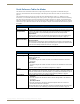
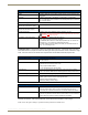
Quick Reference Table 1 – Modes for Handling System Architecture
Mode Description
DXLink Fiber Mode
(Endpoint Mode)
The DXLink Fiber Mode refers to the type of physical components and how they are connected
to make up the system. When DXLink Fiber Transmitters and Receivers are cabled into a
system and powered on, they automatically detect the DXLink Fiber Endpoint Mode.
Endpoint Mode:
When the system is setup to use Transmitters and/or Receivers with an Enova DGX Digital
Media Switcher enclosure, the system is in Endpoint Mode (see example on page 35).
Directional Mode
(Bidirectional Mode)
Directional Mode refers to the flow of data within the system.
Bidirectional Mode:
When data flows in two directions, the flow is bidirectional. For example, a signal travels from
the TX to the RX in Endpoint Mode (through the switcher) and a signal from an HID connected
to the RX via the USB port travels back to the TX – see page 47.
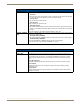
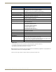
Quick Reference Table 2 – Modes for Handling Addressing/Networking
Mode Description
IP Addressing Mode
IP Addressing Mode refer to network connection settings. By default, all network connection
settings are turned OFF.
Static IP Mode:
• This mode configures the network connection to one stable IP address the unit will use
continuously.
DHCP Mode:
• This mode configures the network connection to choose a new IP address for each network
session.
To enable network capability, see “Network Configuration” on page 54.
ID Mode
ID (Identify) Mode refers to the protocol for enabling a user to establish device addresses. This
Mode, accessible through NetLinx Studio, places the entire system on hold while it waits for an
event from a NetLinx device in the named system (e.g., pressing the ID Pushbutton on the TX
or RX). For further information, see “Assign a Device Address (ID Mode)” on page 58.
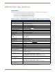
Ethernet Mode Ethernet Mode refers to the LAN configuration settings.
Auto Mode:
• This mode configures the LAN driver to discover its own settings based on the network it is
connected to.
Speed/Duplex Mode:
• This mode configures the LAN driver to calculate its speed as either 10 or 100 and to
communicate in either half- or full-duplex.
Ethernet Mode discovery and configuration information is available through Telnet commands.
For further information, see “Establishing a Terminal Connection Via Telnet” on page 93.