instruction manual 8.
AMX Limited Warranty and Disclaimer AMX Corporation warrants its products to be free of defects in material and workmanship under normal use for three (3) years from the date of purchase from AMX Corporation, with the following exceptions: • Electroluminescent and LCD Control Panels are warranted for three (3) years, except for the display and touch overlay components that are warranted for a period of one (1) year.
Table of Contents Table of Contents Product Information .................................................................................................1 Specifications .................................................................................................................... 1 Cleaning the Touch Overlay.............................................................................................. 2 Installation .....................................................................................
Table of Contents System Send_Commands .............................................................................................. 21 Programming Numbers ................................................................................................... 26 Shorthand Send_Commands.......................................................................................... 27 Color Send_Commands..................................................................................................
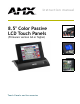
Product Information Product Information The Color Passive-Matrix touch panels contain an 8.5" (215.90 mm) 256-color passive-matrix liquid crystal display (LCD). The self-contained enclosures use a microprocessor to control a wide range of multimedia equipment. Using the TPDesign3 Touch Panel design program, you create custom pages with buttons, icons, sliders, bargraphs, time displays, logos, and drawings. 8.
Product Information Specifications (Cont.) Enclosure: AXD-CP Metal sub-plate and bezel with black or white matte finish AXT-CP TiltScreen tabletop console; black plastic with matte finish AXM-CP 19" (48.3 cm) Unimount; metal with black matte finish (4 rack units high) Accessories Included • 12 VDC power supply, 1.
Installation Installation Mounting the Touch Panel The following paragraphs describe mounting the Decor and rack-mount touch panels. TiltScreen touch panels can be placed on any flat surface. Decor style panels with low-profile Back Boxes 1. Cut out the surface using the dimensions shown in FIG. 1. FIG. 1 Decor style and low-profile Back Box output dimensions 2. Carefully insert a flat-blade screwdriver into the release slot on the touch panel's faceplate and remove the engraved overlay. 3.
Installation 6. Fasten the low-profile Back Box to the surface using the #6-32 machine screws supplied with the enclosure. 7. Attach the data and power wiring to the touch panel. 8. Test the connection by reconnecting the AXlink connector to the Central Controller and optional RS-232 wiring to the source equipment. Before continuing, disconnect all connections until panel installation is complete.
Installation FIG. 3 Decor style (AXD) and BB-TP2 cutout dimensions The touch panel must always be installed with the release slot located at the bottom. 2. Carefully insert a flat-blade screwdriver into the release slot on the touch panel’s bezel and remove the engraved overlay. 3. Lay the touch panel facedown onto a soft cloth and remove the four screws from the lowprofile Back Box. Remove the Back Box and discard. 4.
Installation 11. Test the connection by reconnecting the AXlink connector to the Central Controller and the optional RS-232 wiring to the source equipment. The panel beeps upon power-up. Before continuing, disconnect all connections until panel installation is complete. 12. Fasten the touch panel to the BB-TP2 using the #6-32 screws supplied with the panel. 13. Place the Decor-style faceplate onto the bezel. You can also secure the faceplate to the bezel using the four Phillips flat-head security screws.
Installation FIG. 5 Decor style (AXD) and BB-TP2 cutout dimensions for plasterboard 8. Thread the incoming AXlink and RS-232 wiring through the BB-TP2 knockouts. Refer toWiring the Touch Panel section on page 8 for more information. 9. Fasten the BB-TP2 to the plasterboard using the expansion screws supplied with the enclosure. 10. Connect the AXlink and RS-232 wiring to the touch panel. 11.
Installation Rack-mount panel (AXM-CP/PB) 1. Thread the incoming AXlink and optional RS-232 wiring through the opening in the equipment rack. 2. Disconnect the AXlink connector from the Central Controller and disconnect the optional RS232 connector from the external RS-232 device connected to the touch panel. 3. Insert the touch panel into the equipment rack. Line up the top-left and bottom-right screw holes and start tightening the #6-32 screws. Then, tighten the bottom-left and top-right screws. 4.
Installation Wiring guidelines The touch panels require 12 VDC power to operate properly. The Central Controller supplies power via the AXlink cable or external 12 VDC power supply. The maximum wiring distance between the Central Controller and touch panel is determined by power consumption, supplied voltage, and the wire gauge used for the cable. The table below lists wire sizes and the maximum lengths allowable between the touch panel and Central Controller.
Installation 12 VDC power supply PWR (+) GND (-) PWR (+) AXP AXM GND (-) PWR (+) AXP AXM GND (-) Central Controller AXlink connector on the touch panel FIG. 9 AXlink and external 12 VDC power supply wiring diagram Using the (DB-9) RS-232 connector for mouse control or data The dual-function (DB-9) RS-232 connector supports most standard serial mouse control devices and RS-232 communication protocols for PC data transmission.
Designing Touch Panel Pages Designing Touch Panel Pages There are two ways to approach creating touch panel pages: ! TPDesign3 - Refer to the TPDesign3 Touch Panel Program (Version 3. 16 or higher) Instruction Manual for more information. ! On-board editor This document describes basic use of the on-board editor to create pages and buttons. Refer to the G3 Firmware Design and Reference instruction manual for more detailed firmware information.
Designing Touch Panel Pages General Button Categories (Cont.) Status buttons Status buttons always have a black fill with white letters and have no functionality except to display information. Operation bars Operation bars appear in the place of the Editor bar, after selecting a button or page edit operation. The operation bar indicates which edit function is currently active. When an edit operation is selected, it remains active until you press EXIT.
Designing Touch Panel Pages To activate edit mode: 1. Press SETUP in the Main page to open the Setup page (FIG. 12). FIG. 12 Setup page 2. Press PROTECTED SETUP to open the keypad. 3. Enter 1988 (default password) in the keypad and press ENTER to open Protected Setup page. If you press ENTER after typing an incorrect password, you are immediately returned to the previous page. 4. Press EDITOR to enable Edit mode. The EDITOR button is highlighted in the Protected Setup page when enabled, as shown in FIG.
Designing Touch Panel Pages Edit bar FIG. 14 Main page with Edit bar Setting the Device Base Press the DEVICE BASE option, in the Protected Setup page (FIG. 13), to assign a base (starting) device address to the touch panel. 1. Enter the base address for the touch panel. The base address range is from 1 - 255. Standard device addresses begin at 128. 2. Press Enter to save. Setting the Device Used Use the DEVICE USED option in the Protected Setup page (FIG.
Designing Touch Panel Pages Adding a Button To add a button to the current page: 1. Press BUTTON on the Edit bar to open the BUTTON menu. 2. Press ADD to open the ADD BUTTON operation bar. On the LCD screen, touch and drag to create a button. The first touch point is the upper-left corner of the button. Resizing a button 1. Press BUTTON on the Edit bar to open the BUTTON menu. 2. Press RESIZE. Then, touch any edge of the button and drag. Removing your finger from the panel saves the button dimensions.
Designing Touch Panel Pages 2. Enter 1, 2, 3, or 4 in the keypad. The programming software uses device codes 1 - 4 to identify the touch panel. Refer to the G3 Firmware Design and Reference instruction manual for more information. If DEVICE USED is set to 4 and Base Device Number is 128, the Controller recognizes bus devices 128 - 131. The panel will not allow you to enter a device number greater than the DEVICE USED without first displaying a decision box asking if you accept the new selection or not. 3.
Designing Touch Panel Pages Setting the button colors for channel-off conditions 1. Press any button to open the Button Properties page. 2. Press BORDER under CHANNEL OFF in the Button Properties page. The color palette appears. Select a color to set as the border. 3. Press the FILL button in the Button Properties page to open the palette. Select a color to set as the fill. 4. Press the TEXT button to open the palette. Select a color to use for the text. 5.
Designing Touch Panel Pages 6. In the What To Send area, select one or more of the available options (All Bitmaps, All Icons, All Fonts). 7. Select the mode of communication with the touch panel (RS-232 and AXlink). Confirm that the correct panel is selected by verifying the ID values with the Base Address assigned to the touch panel in the Protected Setup page. 8. After clicking Connect, the Available Panels list appears in the Available Panels field.
Designing Touch Panel Pages 4. Press NUM to open a keypad and set the level number assigned to the device. 5. Enter a number 1 – 8. Each device can have from 1 – 8 levels except joysticks, where the range is 1 – 7. 6. Press ENTER to save, close the keypad, and return to the Button Properties page.
Designing Touch Panel Pages 20 Color Passive-Matrix LCD Touch Panels
Programming Programming You can program the touch panel to perform a wide variety of operations using AXCESS Send_Commands and variable text commands. Use the commands described in this section to program the touch panel. System Send_Commands System Send_Commands are stored in the Controller and direct the touch panel to perform various operations. System Send_Commands ABEEP Syntax: Outputs one panel "’ABEEP’" beep even if the Example: beep value is set SEND_COMMAND TP, "’ABEEP’" to 0 in the Setup page.
Programming System Send_Commands (Cont.) BEEP The Beep button in the Protected Setup page must be set from 1 - 10 for the BEEP comGives an output of mand. one beep. Syntax: "’BEEP’" Example: SEND_COMMAND TP,"’BEEP’" Beeps the panel if the Beep button is not set to 0. BRIT Adjusts brightness of display. Syntax: "’BRIT-’" Variables: level = 1 - 5 (1 = minimum; 5 = maximum) Example: SEND_COMMAND TP,"’BRIT-5’" Sets to highest brightness level. CONT Adjusts brightness of display.
Programming System Send_Commands (Cont.) PAGE Syntax: Flips to page with specified page name. Variables: "’PAGE-’" page name = 1 - 50 ASCII characters Example: SEND_COMMAND TP, "’PAGE-MAIN PAGE’" Flips the touch panel to the page named MAIN PAGE. PKEYP Syntax: Displays asterisks (*) for keypad entries. Variables: "’PKEYP-’" number string = 0 - 9999 Example: SEND_COMMAND TP, "’PKEYP-1988’" Displays the touch panel keypad with **** instead of 1988.
Programming System Send_Commands (Cont.) SLEEP Syntax: Forces the touch panel to screen saver mode. Example: "’SLEEP’" SEND_COMMAND TP,"’SLEEP’" Activates the screen saver mode. $SC Sends a serial port send_command within a panel, as if sent from Axcess. Syntax: "$SC ,"’,,’"" Variables: device offset = Device number variable text # = The variable text number value on the touch panel.
Programming System Send_Commands (Cont.) TPAGEON Activates page tracking.
Programming Programming Numbers The following information provides the programming numbers for colors, fonts, and borders ! Colors can be used to set the colors on buttons, sliders, gauges, and pages. The lowest color number represents the lightest color-specific display; the highest number represents the darkest display. For example, 0 represents light red, and 5 is dark red. Colors and Programming Numbers ! Color No. Color No.
Programming Shorthand Send_Commands The table below lists the shorthand Send_Commands you can use with touch panels. The shorthand command data is 1-byte, non-ASCII format except for pages, passwords, text, and bitmap names. Shorthand Send_Commands @CBF This works only if the specified background color is not the same as the current color. Sets the OFF feedback border color to the specified color.
Programming Shorthand Send_Commands (Cont.) @CPG This only works if the new background color is not the same as the current color. Sets the page with Syntax: specified page "’@CPG’,,’’" name backVariables: ground color to the specified color number = See the Colors and Programming Numbers table on page 26. color. page name = 1 – 50 ASCII characters Example: SEND_COMMAND TP,"’@CPG’,87,’Main Page’" Sets the page title to Main Page, and the color to Black.
Programming Shorthand Send_Commands (Cont.) @IDP Queries the touch panel to return a string with the TPDesign3 project name. @MOU Sets the serial mouse type. Syntax: "’@IDP’" Example: SEND_COMMAND TP,"’@IDP’" The touch panel returns a string that contains its TPDesign3 project name. Syntax: "’@MOU’," Variables: touch_type = = 0 and = 1 Example: SEND_COMMAND TP,"’@MOU’, 1" Sets the Microsoft Serial Mouse.
Programming Shorthand Send_Commands (Cont.) @PPN If a page name is empty the current page is used. Activates a popup page on a touch panel page. Syntax: "’@PPN-;’" Variables: popup page name = Popup page name page name = Page name Example: SEND_COMMAND TP,"’@PPN-Laser Disc 2 Transport Control; Laser Disc Control Page’" Activates the Laser Disc 2 Transport Control popup page on the Laser Disc Control Page. @PPX Removes all panel popup pages.
Programming Shorthand Send_Commands (Cont.) @SWK Changes the wake-up string sent to the Controller when the touch panel is activated. Syntax: "’@SWK-’" Variables: string = alphanumeric characters Example: SEND_COMMAND TP,"’@SWK-Touch Panel Activated’" Sends Touch Panel Activated to the Central Controller. Color Send_Commands Use the color Send_Commands to set the colors for text, buttons, and pages.
Programming Color Send_Commands (Cont.) CBON Syntax: Sets the ON feed"’CBON-’" back border color Variables: to the specified variable text address = 1 - 255 color. color number = See the Colors and Programming Numbers table on page 26. Example: SEND_COMMAND TP,"’CBON1-87’" Sets the ON feedback border color to Black for variable text button 1. CFOFF Syntax: Sets the OFF feedback fill color to the specified color.
Programming Color Send_Commands (Cont.) CTON Syntax: Sets the ON feed"’CTON-’" back text color to Variables: the specified variable text address = 1 - 255 color. color number = See the Colors and Programming Numbers table on page 26. Example: SEND_COMMAND TP,"’CTON1-72’" Sets the ON feedback text color to White for variable text button 1. Variable Text Send_Commands Use variable text Send_Commands to set the borders, fonts, and text.
Programming Variable Text Send_Commands (Cont.) !C Sets the border, font, and text in one command. Syntax: "’!C’,,,,’’" Variables: variable text address = 1 - 255 border style = See the Border Styles and Programming Numbers table on page 26. font size = See the Font Styles and Programming Numbers table on page 26. button text = Enter button text to appear on button.
Programming Variable Text Send_Commands (Cont.) !T Syntax: Shorthand version of 'TEXT' command. Variables: "’!T’,,’’" variable text address = 1 - 255 new button text = 1 - 60 characters Example: SEND_COMMAND TP,"’!T’,1,’VCR PLAY’" Changes the variable text button one title to VCR PLAY. TEXT Use the | character to display text on multiple lines. Enters text on a button.
Programming Shorthand Variable Text Commands The table below lists the shorthand variable text commands you can use with the touch panel. The shorthand command data is one-byte, non-ASCII format except for pages, passwords, text, and bitmap names. Shorthand Variable Text Commands @BMF This command allows you to program up to 12 attributes on one command line. Syntax: Sets multiple attributes to a but"’@BMF’,,’’" ton, slider, or Variables: gauge.
Programming Shorthand Variable Text Commands (Cont.) @BOR Syntax: Sets the border style on a button. Variables: "’@BOR’,," variable text address = 1 - 255 border style = See the Border Styles and Programming Numbers table on page 26. Example: SEND_COMMAND TP, "’@BOR’,65,11" Sets the border style to Double shadow on button 65. @ENA Syntax: Enables/Disables buttons based on their variable text channel.
Programming Shorthand Variable Text Commands (Cont.) @JUS Syntax: Sets the text alignment on a button. Variables: "’@JUS’,," variable text address = 1 - 255 text alignment = 1 - 9 as shown in the following alignment chart 1 2 3 4 5 6 7 8 9 Example: SEND_COMMAND TP, "’@JUS’,9,5" Centers the text on button 9. @SHO Sets a specific button to on or off.
Programming Button String Commands The table below lists string commands you can assign to buttons using the touch panel editor. Select the PROPERTIES option in the Edit bar, press the target button, and enter the string command with the Touch Panel keyboard. The string command is sent to the control system when you press the button. Button String Commands $ID Sets the WavePack group ID number. Syntax: "’$ID ’" Variables: group ID = 0 (Off) - 15 Example: $ID 15 Sets the Group ID to 15.
Programming Button String Commands (Cont.) $ST When the touch panel’s input time matches the sleep time, the panel goes to sleep. Sets the idle time to activate sleep mode for a touch panel in 1-minute increments. Syntax: "’$ST ’" Variables: sleep timeout = 1 (Off) - 120 (minutes) Example: $ST 5 Sets the touch panel’s sleep time to 5 minutes.
Upgrading the Firmware Upgrading the Firmware In order to upgrade the firmware in the panel, you can either return the panel to AMX or replace the necessary EPROM chips yourself. Standard memory on the G3 boards for the CP series of touch panels is 1 MB of base memory. The EPROM chips are pre-loaded with the firmware, and can be obtained from the factory or dealer, then installed into the touch panel circuit board. AXT-CP EPROM Replacement Remove the EPROMs from the AXT-CP: 1.
Upgrading the Firmware 8. Using the new EPROMs, match up the socket holes to their respective prong and the notches to the correct direction for both the new Odd and Even chips. 9. Insert all the prongs simultaneously until each is firmly resting in its socket hole and the entire chip is securely connected to its base. 10. Rotate the circuit card back to the original position and place it in the touch panel housing. 11.
Upgrading the Firmware 7. Gently pry the EPROMs from their connection base until they begin to loosen. Carefully pull them out by either using an EPROM removal device or by gently pulling them from their base (making sure to evenly pull the prongs from their socket holes). . Insert the EPROMs with the notches facing the correct direction. Match the Even and Odd EPROM placement with the location shown above.
Upgrading the Firmware 44 Color Passive-Matrix LCD Touch Panels
Replacing the Batteries Replacing the Batteries There are two lithium batteries on the touch panel card, with a life of approximately 5 years. They protect stored commands and pages against a power outage. The batteries are not used when DC power is supplied to the touch panel. You should write down the replacement date on a label by adding 5 years to the date of installation, and attach it to the panel for future reference. FIG.
Replacing the Batteries 8. Plug the 2-pin power or AXlink connector back into the touch panel for approximately 1 minute. Then, remove connector from the panel again. 9. Gently tilt the circuit card down towards the connector side and pull backwards until you clear the connector housing. Then, slowly rotate the circuit card backward again until you can lay it down flat with the batteries exposed. 10. Carefully slide the other battery out of its socket, and insert the new battery. 11.
Replacing the Batteries Color Passive-Matrix LCD Touch Panels 47
brussels • dallas • los angeles • mexico city • philadelphia • shanghai • singapore • tampa • toronto* • york 3000 research drive, richardson, TX 75082 USA • 469.624.8000 • 800.222.0193 • fax 469.624.7153 • technical support 800.932.6993 036-004-1794 7/03 ©2003 AMX Corporation. All rights reserved. AMX, the AMX logo, the building icon, the home icon, and the light bulb icon are all trademarks of AMX Corporation. AMX reserves the right to alter specifications without notice at any time.