
Installation manual

Installing the HPX-1600
10
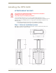
HPX-1600 Retractable Connection Port
Step 3 - Prepare the Terminations
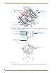
Some modules that are included in the final system require some type of backside termination. Refer to the
installation guide for each module to determine the required backside termination.
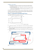
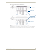
FIG. 6 provides two example illustrations of module backside termination.
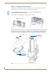
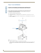
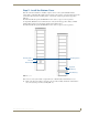
Note that for terminations for which the far end of the cable is not accessible either because the cable has been
run under carpet, in a conduit or structure, or is otherwise fixed, the cable must be placed through the retaining
ring, (note the orientation of the retaining ring - see FIG. 8 on page 11) then through the mounting surface
from bottom to top, then to the module before the module is placed into the base assembly, as shown in FIG. 7:
The backside termination for each module can and should be completed before the
module is installed into HPX Base assembly.
FIG. 6 Terminating Connections of 1 or 2 HPX Modules
FIG. 7 Fixed Cable Passing Through Ring, Table and Into the HPX-1600 Assembly
Terminating Connections -
Terminating Connections -
2 Modules
1 Module
Mounting Surface
Fixed Cables
Retaining Ring
Fixed Cables