
Installation manual

Installing the HPX-1600
13
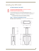
HPX-1600 Retractable Connection Port
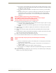
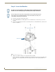
5. Route the cables from each module out the bottom (currently facing up) of the base assembly.
6. If both low-voltage, secondary circuit (LVSC) modules and AC Power Outlets will be installed, place the
(LVSC) modules in the upper portion of the chassis first, followed by the AC Power Outlets in the lower
portion of the chassis.
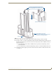
The LVSC Modules and the AC Power Outlets must be separated by the High Voltage Isolators
provided in this kit.
See the Instructions provided with the High Voltage Isolators for detailed installation instructions.
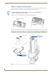
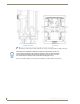
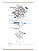
7. For AC power modules, plug the provided wire harness into the Power Inlet assembly inside the bottom
cover (FIG. 11).
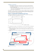
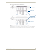
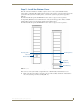
FIG. 10 Inserting Modules Into the HPX-1600 Base Assembly
Top Cover
(detail view of Module Faceplate)
This tab on each Module faceplate must
face the BOTTOM of the Hydraport system
HPX-1600 Base Assembly
(shown here upside-down, as it should be
positioned for inserting Modules)
(bottom)