Vision2 Operation/Reference Guide Operation/Reference Guide 2 ® Vision v8.
AMX Limited Warranty and Disclaimer This Limited Warranty and Disclaimer extends only to products purchased directly from AMX or an AMX Authorized Partner which include AMX Dealers, Distributors, VIP’s or other AMX authorized entity.
AMX Software License and Warranty Agreement • LICENSE GRANT. AMX grants to Licensee the non-exclusive right to use the AMX Software in the manner described in this License. The AMX Software is licensed, not sold. This license does not grant Licensee the right to create derivative works of the AMX Software. The AMX Software consists of generally available programming and development software, product documentation, sample applications, tools and utilities, and miscellaneous technical information.
Table of Contents Table of Contents Overview ............................................................................................................1 Live Channels .................................................................................................................. 1 Vision2 Services............................................................................................................... 1 Components of a Vision2 system ................................................................
Table of Contents Adding a Server to your Vision2 System................................................................. 25 Accessing a Vision2 Server Directly (Troubleshooting only).................................... 26 Changing a Server’s Name...................................................................................... 27 Removing a Slave Server ........................................................................................ 27 Licensing ...............................................
Table of Contents Viewing the Reflector Output Stream ........................................................................... 59 DVB Service ......................................................................................................61 Configuring a DVB Tuner Service............................................................................ 61 Configure Tuner Hardware Settings..............................................................................
Table of Contents Configuration.......................................................................................................... 91 Recording a Video Stream............................................................................................. 92 Manual Recording ................................................................................................... 93 Scheduled Recording ..............................................................................................
Overview Overview Vision2 is a sophisticated, fully-integrated video capture, management, and broadcast system for organizations and homeowners wanting a comprehensive, yet simple-to-use, IP video delivery solution. Vision2 offers live, scheduled, or on-demand video, all managed from a convenient web interface.
Overview Components of a Vision2 system A Vision2 system can consist of one or more Vision2 servers. One of the Vision2 servers must be set as the master server, the other servers known as slaves are subordinate to this server. Typically a V2-MASTER-xxxx server is used as the Master server but it is possible to use other servers as the master server in smaller installations. User access the Vision2 user interface through a web page on the master server, http:///v2.aspx.
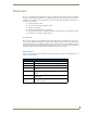
Overview Server Specifications The following table lists the specifications for the V2-SERVER-0300 (FG3106-03), V2-SERVER-1200 (FG3106-12), V2-SERVER-2400 (FG3106-24), and V2-SERVER-3600 (FG3106-36) servers: V2-SERVER Specifications Processor: 2 x Intel® Xeon® E5-2620, 2.00 GHz processors Memory: 16GB RAM Storage (available): • 1.8 TB (7.2K RPM) (V2-SERVER-0300, FG3106-03) • 9.1 TB (7.2K RPM) (V2-SERVER-1200, FG3106-12) • 18.2 TB (7.2K RPM) (V2-SERVER-2400, FG3106-24) • 27.3 TB (7.
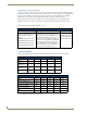
Overview Vision2 Expansion Storage The Vision2 Expansion Storage V2-STORAGE-2400 (FG3102-01) is an optional accessory that connects directly to your Master server to allow you to grow the storage capacity of your system. The Expansion Storage is shipped in a RAID configuration in order to provide resiliency in the event of a disk failure. The following table lists the specifications for the V2-STORAGE-2400 Expansion Storage (FG3102-01): V2-STORAGE-2400 Expansion Storage Specifications Storage: 12 2TB 7.
Overview Audio: • Analog stereo audio out • Stereo and Dolby 5.1 surround via S/PDIF and HDMI • Dolby Digital+ pass through to external decoder Operating Environment: • Operating Temperature: 0º to 40º C (32º to 104º F) • Storage Relative Humidity: 5% to 95% (non-condensing) Dimensions (HWD): 1 9/16" (4cm) H x 5 1/2" (14cm) W x 4 1/2" (11.4cm) D Weight: 0.70 lbs (0.
Overview FIG.
Wiring and Device Connections Wiring and Device Connections V2-Master Server Rear Panel Connections This section details the ports and connectors on the rear panel of the Vision2 Master server. Output port Power connector LAN ports FIG. 2 Vision2 Master server rear panel The two flex drives at the rear of the V2-Master server are fitted with 146GB 15K SAS 2.5in Hot-Plug Drives configured as Raid1 for the OS (Microsoft Windows Server 2008 Standard) LAN (RJ-45) Port FIG. 3 LAN (RJ-45) Port FIG.
Wiring and Device Connections 6 RX - 6 --------- 6 7 no connection 7 --------- 7 8 no connection 8 --------- 8 Green 7 --------- 8 Brown-White Brown FIG. 5 diagrams the RJ-45 pinouts and signals for the LAN RJ-45 connector and cable. FIG. 5 RJ-45 wiring diagram Set-Top Box Connections The STB-04 Set-Top Box (FG3100-65) supports viewing the Live Channels from MAX CSE Encoders, Producers, Reflectors, or DVB Tuners.
Installation Installation This section provides instructions on how to install the different Vision2 accessories. Installing Master Servers Accessories You can install optional accessories into your Master server for redundant power or for connection to an Archive server. Installing a Secondary Power Supply The V2-POWER-1100 (FG3106-PS) is a secondary power supply that you can use to add redundant power to FG3106-XX Vision2 Master Servers. Master servers ship with a single 1100W power supply.
Installation FIG. 9 Vision2 Archive/Video on Demand server with V2-PVA (rear-view) FIG. 10 V2-STORAGE-2400 Expansion Storage (rear-view) Set-Top Boxes The STB-04 (FG3100-65) Set-Top Box supports viewing live programming via a Producer channel, MPEG encoder, or DVB Tuner channel. The set-top boxes access your Vision2 server and display available programming on a connected video source. The set-top boxes are used only for MPEG2 and MP3 content.
Installation Use an HDMI cable to connect the HDMI port on the set-top box to an HDMI port on your video source. HDMI also transmits an audio signal in addition to video. Use a breakout cable to connect the AUDIO VISUAL port on the set-top box to your audio and video sources. In place of connecting the breakout cable to your audio source, you can connect an optical audio cable from the SPDIF port on the set-top box to your audio source. 3.
Installation Setup networking on your set-top box as follows: 1. Select the DHCP menu 2. Change the DHCP setting to disabled 3. Enter an IP address, Netmask, Gateway and (optional) DNS server setting for your set top box FIG. 14 Network Settings Set the browser home page for your set-top box to point to a page on your Vision2 master server: 1. Use the arrow keys on the keyboard to access the Browser option, and press the right arrow cursor key to enter this page (FIG. 15). FIG.
Installation Configure the video settings as follows: 1. 2. 3. 4. Return to the User Prefs menu and select the Video page, see FIG. 16 Change the TV type setting to the correct aspect ratio for the attached display e.g. 16:9 Change the output resolution to the resolution supported by your set top box e.g. 720p50 Select the back option and choose yes to return to the main menu FIG. 16 Video Settings Now restart your set top box, select Restart followed by Yes and press Enter to reboot the set-top box.
Installation Subtitles are only supported on DTV streams. If you are using an STB-04 set-top box and you receive a "failed to load webpage" error, select the OK button on the remote and, using the remote, power the set-top box off and on again. Afterward, the Vision2 main menu loads. After the set-top box reboots, it accesses the Vision2 master server you indicated and downloads the latest Vision2 menus.
Installation FIG. 19 Live TV Channels FIG. 20 Video On Demand Section - List of Archives FIG. 21 Selecting a Video to Play playback. Use the Play button to resume viewing a paused video stream. To refresh your set top box to display new content in your archive or to refresh the template displayed, navigate away from the main menu into the Live Channels or Video on Demand pages and press and hold the menu button for a second or more, the screen should flash and then you will be returned to the main menu.
Installation FIG. 22 Video Metadata FIG. 23 Video playback and seek bar The set-top box also has a search feature, select the search icon and click OK to open the search dialogue box, see FIG. 24. Enter the text you want to search for and click GO, this returns any matching videos. Note that the search is case-insensitive. FIG.
Vision2 User Interface Vision2 User Interface This section provides a brief overview of the Vision2 User interface, it contains the following Vision2 User Interface Requirements - Software and plugins needed to use Vision2 Accessing the Vision2 User Interface - Explains how to access the Vision2 User interface Vision2 Menu Structure Access Control Loading and Enabling Vision2 services Vision2 User Interface Requirements PC Users who wish to connect to Vision2 must be aware that the interface has
Vision2 User Interface VLC version 2.0.6 is not supported Accessing the Vision2 User Interface For the First Time Perform these steps to access your Master Server for the first time: 1. Power on your Vision2 server. It may take a few minutes to boot. 2. Test that you can access the server via the LAN. You can run this test by accessing a Command Prompt using the Ping command. For example: ping v2AMX-xxxxxxxx where v2AMX-xxxxxxxx is the master server name 3.
Vision2 User Interface You must reboot your server after converting it to a master server or you will be unable to license the server Vision2 Menu Structure The Vision2 menu has the following components: Menu Structure Menus Sub Menus Description Recent Updates See the 100 most recent updates in each archive Browse Play Video on Demand Archives Upload Videos Manage Videos Configure Archive Setup Archive (Administrator only) Archive Permissions (Administrator only) Used to determine which users
Vision2 User Interface Edit Schedule Edit Schedule for Producer Channel Configure Recorder Configure a Record Service, choose which Live Channel to record and whether to do a manual, continuous or scheduled record Manual Recording Start and Start a Manual Record Schedule Recording Edit Record Schedule Video Recorders Manage System - Administrator only Manage Servers Add/Remove servers to/from your Vision2 system Manage Licensing Allocate/Remove Vision2 service licenses to/from your servers Vie
Vision2 User Interface 4. Go to Manage System > V2 Services Permissions and Enable V2 Service User Access control, access to all service pages (Reflector, Recorder, Producer, DVB tuner, and MAX CSE encoder) is now restricted to users with permissions set in this screen. As user bob has no permissions for these services, he has no access to these screens. 5. Login to the Vision2 user interface in a second browser tab by entering the standard URL, http:///v2.
Vision2 User Interface Loading and Enabling Vision2 Services The typical steps the user must follow to load and enable Vision2 services are as follows: 1. Select a service 2. Click Load to load the service details. Note once you load a service then you gain a lock on that service. This lock prevents any other users from modifying settings on this page and interfering with your work. 3. Configure the service by changing the settings to the required values.
Vision2 User Interface 1. Login as the Administrator, select the appropriate menu tabs for the service. Select the locked service using the Select a Service drop down and click Load. You will be told that this service is currently locked and will be given details of the user who has the lock 2. Click manual unlocking to release the lock, any user can now access the service. FIG. 31 Manually Unlocking a Locked Service Renaming a Service.
Vision2 User Interface 24 Vision2 Operation/Reference Guide
Server Management Server Management This section provides information on managing multiple Vision2 servers. Overview In small Vision2 systems you will only have one server, the Master server. However larger installations will have two or more servers. In this case one server is configured as a Master server and the other servers are known as Slave servers as they are subordinate to the Master server. Vision2 services can run on any server but are controlled through the master server.
Server Management FIG. 33 Adding a Slave Server to Vision2 System Accessing a Vision2 Server Directly (Troubleshooting only) Perform these steps to access your server directly: 1. Connect a monitor to the VGA port on the front of the server. 2. Connect a USB keyboard and USB mouse to the 2 USB ports on the front of the server. There is also a 15-pin VGA port and 2 USB ports on the rear of the server. It makes no difference which set of ports you use to connect your peripherals. 3.
Server Management Changing a Server’s Name You can change your server’s name from the default name assigned to it. After changing the name, use the new server name to access the Vision2 application. Perform these steps to change your server’s name: 1. On your server’s desktop, close the Vision2 server application. 2. On your server’s desktop, click Start, right-click Computer, and select Properties. The System Properties window opens. 3.
Server Management 28 Vision2 Operation/Reference Guide
Licensing Licensing This section explains how to License your Vision2 system and allocate Licenses to your Vision2 servers. There are three typical steps to licensing a Vision2 system: 1. Obtain a License Entitlement ID for your Vision2 system from AMX. 2. Use the License Entitlement ID with the AMX License Manager on your Vision2 Master server or a local Network License manager to activate your license. 3.
Licensing FIG. 36 Select License Server Choose one of the Select License Server options: Use the local license server installed and running on this machine - This is the default option. Search the network for available license servers - Use this option if the AMX License Server application is already installed on your network, for example if you have other AMX products.
Licensing FIG. 37 Licensing Options Dialog 2. This selection opens the Contact Information window, enter your contact information. Note If you already have an amx.com account, click on Lookup Account to provide your credentials (email address and password) to automatically populate the contact information for this license based on your existing AMX account information. 3. Click Next to proceed to the Customer Information window. Select your industry sector from the drop down menu. 4.
Licensing FIG. 38 Enter Entitlement ID 4. Choose the product to license, in this case Vision2Choose either a local License Server (default option) or a network license server. Use the same option that you used when installing Vision2 5. 6. 7. 8. 9. 10. 11.
Licensing Vision2 License Management Screen Login to the Vision2 user interface using Internet Explorer and go to http:///v2.aspx where server name is the name of your Vision2 master server. Go to Manage System > Manage Licensing to open the License Management Screen, see (FIG. 39) FIG. 39 License Management The screen consists of two columns.
Licensing Adding a License to a Vision2 Server To add a license to a server, click on the row for the particular license in the System License table and drag and drop the license onto the Server. licenses are ordered by type on the server, click the arrow to the left of the license name to view all the licenses of this type. Click arrow to expand and view list of licenses of this type Number of licenses of this type Service disabled Service enabled FIG.
Licensing Rules for V2-Master-XXXX Servers This is the only server type which supports Archive services. The server can support a maximum of 300Mbits/s VOD bandwidth. You cannot add a Producer/Record service to the server unless there is at least one archive in the system. You cannot add more VOD Bandwidth to a server unless there is at least one archive on the server.
Licensing 36 Vision2 Operation/Reference Guide
Manage System Manage System We have already discussed two sub menus contained in the Manage System menu, Licensing and Managing Vision2 servers, Manage Servers and Manage Licensing. This section of the manual discusses the remaining sub menus. View Logs The view logs screen is used to view the logs for Vision2 services and for your Vision2 servers.
Manage System User Interface Configuration The User Interface Configuration screen allows the administrator to configure the background screen and cursor colours, etc for Set-top box and tablet users, this is known as the template. There are two columns in this screen: On the left is a column used to configure the Tablet background. Use the Templates drop down menu to select a new template.
Manage System FIG. 43 Template Editor - Main screen Device and Template Options Device Select a device from the available list to view its template. Any new devices you add appear in this list. Add New Device Click to add a new device to the template list. See Adding a New Device to the Device List section on page 38 for more information. Delete Device Click to delete the currently selected device. You will receive a confirmation warning before deleting the device.
Manage System FIG. 44 Add New Device options Creating a New Template Perform these steps to create a new template: 1. Click Create New Template. A series of options appears (FIG. 45). FIG. 45 Create a New Template 2. Enter the name of the template in the Template Name field. 3. Use the Create new template as a copy of options menu to select the model of template you want to use. 4. Click Create.
Manage System FIG. 46 Template Editor Settings Template Settings Navigation: Menu Selector Color Use the color chart to select a color for the menu selector. Render top line navigation Click the check box to render the text on the navigation bar. Color Use the color chart to select a color for the text on the navigation bar. Font Size Use the spin box to indicate the size of the text on the navigation bar. You can set any value between 1 and 255.
Manage System Background Alpha Use the spin box to indicate the alpha used to create the background gradient. You can set any value between 0 and 255. Columns Use the spin box to indicate the number of columns on the navigation pages. You can set any value between 1 and 255. Rows Use the spin box to indicate the number of rows on the navigation pages. You can set any value between 1 and 255. Corner Radius Use the spin box to indicate the size of the corner radius of each thumbnail.
Manage System Background Color 1 Use the color chart to indicate the first color used to create the background gradient. Note: The gradient values are used to create a gradient 'wash' over the main info image to allow text to be more easily visible. Background Alpha 1 Use the spin box to indicate the first alpha used to create the background gradient. You can set any value between 1 and 255. Background Color 2 Use the color chart to indicate the second color used to create the background gradient.
Manage System FIG. 48 displays the location of the info header on the user interface. Info Heading FIG. 48 User Interface Example 2 Set-Top Box Management Set-Top Boxes support Live Channels or Video on Demand. and supports Stop, Play, Pause, Fast-Forward, and Rewind features. See the Set-Top Boxes section on page 10 for information on setting up a set-top box. FIG. 49 displays the Set-top Box Management screen. The Available Set-Top Boxes area lists the set-top boxes FIG.
Manage System currently detected. This list includes the name, status, channel type, and IP address of each set-top box. This list is view-only. You can select any set-top box from the list and use the options below to change its output. You can also use Ctrl-Click to select multiple set-top boxes and Shift-Click to select a range of set-top boxes. The set-top box management options are as follows: Set-Top Box Management Options Name Enter a name for the set-top box.
Manage System Users can login without entering their domain name, for example user bob who is a member of the domain AMX can login using bob rather than AMX\bob. Now you have enabled LDAP it is recommended that you restrict access to your V2 services. Go to Manage System > V2 services permission and enable V2 services access control. You will also need to restrict access to your Archives, go to Archive > Archive Permissions and enable Archive User Access control on each of your Archives.
Manage System Click on a folder or item in the Group Name column to set the LDAP Base DN to the Path value for the currently selected item. Expand the folders if necessary to view the contents. Click Validate to check the new Base DN is an OU and to navigate down the LDAP hierarchy until you find a level where you can view the user groups in your organization that you wish to give access to specific archive folders or Vision2 services.
Manage System FIG. 51 User group Users have permissions to Enable/Disable MPEG Recorder1 and change service name The user only has access to these sections of the Recorder Configuration page all other configuration sections are greyed out FIG. 52 Example to show the effect of Vision2 service permissions set in FIG.
Manage System VOD Bandwidth The VOD bandwidth page, Manage System > VOD Bandwidth is used to view your bandwidth usage and see whether it is exceeding the limits set by your license. There are three tabs at the top of the page: System Report - shows the vod bandwidth and multicast bitrate usage for your whole system. Server Report - shows the vod bandwidth and multicast bitrate usage for a selected server. Configuration - used to select which network interface card to monitor on each server.
Manage System Drag to zoom Drag bar to pan FIG. 54 Zooming in on a region of the VOD bandwidth graph Configuration The configuration tab is used to select which network interface card to monitor on each server. The table contains a list of the servers in your Vision2 system and a selected NIC column. Use the drop down icon in the selected NIC column to choose the IP address of the network interface card you wish to monitor on that server. FIG.
Manage System FIG. 56 Manage Channel Order The following options are available on the Manage Channel Order page. Manage Channel Order Options Add Unmanaged Channel Adds an unmanaged channel to the Channel Order list. Channel Name The name of the channel as it will appear in the Channel Order list. Type The type of stream for the channel. Channel URL Delete Unmanaged Channel The URL of the video source. Removes an unmanaged channel from the Channel Order list.
Manage System MPEG h264 Video HD h264 video streams are not supported 4. Enter the Channel Name 5. Enter the channel URL for the Windows Media Stream or the multicast address and port for MPEG 2 or MPEG h264 channels. 6. Click Add, the channel will now appear in the list 7. Click Save Changes to confirm the changes.
Live MPEG MAX CSE Encoder Service Live MPEG MAX CSE Encoder Service The Vision2 Live MPEG Max CSE Encoder Service is used to control a MAX CSE encoder and view its output as one of your Vision2 Live Channels, this allows users to add a analogue video source such as a camera to your Vision2 system. Once you have configured the Encoder you can use the Live channel it creates as a source for a Record Service or for display as part of a Producer channel.
Live MPEG MAX CSE Encoder Service 3. In the Username text box enter the username used to gain access to the encoder. The default username is Admin. 4. In the Password text box, enter the password used to gain access to the encoder. The default password is 1988. 5. Click Apply. If you have entered the correct details then the Encoder Settings section will update to the values configured on your encoder.
Live MPEG MAX CSE Encoder Service Encoding Settings Options Video Input The MAX encoder supports either S-Video or Composite video inputs. Video Standard The MAX encoder supports the NTSC (USA and Japan) and PAL (rest of the world, excluding France) video standards. Aspect Ratio The MAX encoder supports a 4:3 and 16:9 aspect ratio. Encoder Profile Vision2 only supports the MAX Custom encoder profile. Video CODEC Vision2 only supports MPEG-2 video compression on the MAX encoder.
Live MPEG MAX CSE Encoder Service 56 Vision2 Operation/Reference Guide
Reflector Service Reflector Service The Vision2 Reflector Service is used for the following tasks: To unicast a local MPEG 2/ MPEG 4 h264 Vision2 channel over the internet (multicast streams cannot travel over the internet) so that remote users can view this channel, this could be to a remote Vision2 installation. To receive a unicast MPEG 2/ MPEG 4 h264 Vision2 stream from a remote Vision2 installation and broadcast this as a local live channel. To add an external source e.g.
Reflector Service MPEG Reflector Service Options (Cont.) Service Name The name of the channel to display in the Live Channel list for PC or Set-top box users. Note: this only applies to multicast streams, unicast streams cannot be viewed in the Live Channels list Source Type Click the appropriate option button to indicate the source type. You can choose from either a Local Vision2 Channel or an External Source. V2 Channels The options menu provides a list of all the live channels in the system.
Reflector Service 3. Choose whether the source is a Live Channel or an external source by clicking the Local V2 Channel or External Source option button. If you select Local V2 Channel, select the source Live Channel from the V2 Channels drop down menu. If you select External Source, enter the URL of an address containing an MPEG-2 or H.264 video stream in the URL text box. 4. Click the Multicast option button to select a multicast stream. 5.
Reflector Service 60 Vision2 Operation/Reference Guide
DVB Service DVB Service The Vision2 DVB Service provides and manages a single Digital Video Broadcast (DVB) multiplex of live TV channels to the system. Terrestrial, satellite, and cable TV providers now use a digital rather than analog transmission systems to deliver their content. Where previously a single frequency was required for each TV channel, by using digital compression, multiple channels can be provided on a single frequency (known as a multiplex or bouquet).
DVB Service FIG. 63 Multicast Settings 2. Enter the base multicast address in the Base Multicast Address text box. All channels you choose to transmit are multicast using IP addresses which are offset from this address. For example, if the Address is set to 234.0.0.0, the first channel in the select to transmit table is multicast on 234.0.0.0, and the second 234.0.0.1, etc. 3. Enter the port that you want to multicast the output streams on in the Port text box. 4.
DVB Service Transmit Selected Channels This section describes how to transmit DVB Tuner channels on your network. Users can view these channels in the Live Channels menu, or from set-top boxes attached to your system. The process is as follows: 1. In the Select Channels to Transmit Table, click the check box in the Multicast column for the channels you want to transmit. This channel will now be added to the list of Live Channels that can be viewed by PC or Set-top box users.
DVB Service 64 Vision2 Operation/Reference Guide
Archive Service Archive Service The Vision2 Archive service provides a multi-format, multi-bitrate storage system for video or audio files. Video in the archive can be accessed on demand by PC users, from tablets, or set-top boxes. Users can attach metadata to each video containing information about the video contents, this metadata can be customized by the system administrator.
Archive Service 3. Double-click an Archive license to configure that Archive. If you are not using a NAS archive you will not need to change Archive configuration settings other than the Service Name (this is the name used for this Archive in the User Interface). The Configure Archive screen contains the following options (FIG. 65): FIG.
Archive Service Setting Up a NAS Archive A NAS archive requires a Vision2 server running release 8.2.4327 or greater. To configure the NAS server: 1. Create a folder on the NAS that you want to use to store your archives contents, for example: ArchiveNAS, so that the UNC path to this folder is \\NASservername\ArchiveNAS. 2. Create the user “v2system” with password “Vision2” and give read and write permissions for the ArchiveNAS folder. To configure the Vision2 server: 1.
Archive Service 8. In the v2system Properties dialog (FIG. 67), remove Users from the list, and click Apply. You can close the Computer Management dialog. FIG. 67 Remove Users from the Member of list 9. 10. 11. 12. 13. 14. 15. In Windows, select Start > Control Panel > Administrative Tools > Services. Stop the AMX V2RTSP and AMX Vision2 services. Right-click AMX V2RTSP and select Properties from the context menu that opens. In the Properties dialog that appears, select the Log On tab.
Archive Service 17. Repeat steps 11-16 for AMX Vision2. When finished, you can close the Services dialog. Do not restart these services at this time. 18. In Windows, select Start > Control Panel > Administrative Tools > IIS Manager. 19. Select Connections > Sites > Default Web Site > v2. You will see a folder titled Archives. 20. Right-click the Archives folder, and select Add Virtual Directory to open the Add Virtual Directory dialog (FIG. 69). 21. In the Alias text box, enter “ArchiveNAS”. 22.
Archive Service 25. Click Test Settings and confirm the user is valid and the path is accessible. Click Close. FIG. 71 Test Connection dialog 26. 27. 28. 29. In the IIS Manager, select Connections > Application Pools. Right-click V2AppPool and select Advanced Settings. Under Process Model, select Identity and click the Browse (...) button. Select Custom Account. Click Set, and enter “v2system” for the user name and “Vision2” as the password for the NAS User account.
Archive Service 33. Select Manage System > Manage Licensing. If you are configuring a NAS archive perform the following steps: 34. Drag an Archive license onto the server you want to host the NAS Archive. This must be on the same server on which you have performed the above configuration. 35. Double-click the New Archive license to configure the Archive (FIG. 73). FIG. 73 Configure Archive 36.
Archive Service Configuring a SAN Archive San Archives are configured in a similar way to NAS Archives. Before starting, check that theVision2 server that you want to use to host the SAN archive has permission to read/write from the SAN. Next map the SAN as a network drive on this server using the I drive (note windows search is set on the I drive so do not use another drive letter).
Archive Service The recommended bitrate for high-definition VC1 is 8-12 Mbits. MPEG-2 MPEG-2 must be encapsulated in an MPEG-2 transport stream. The supported audio formats are: MPEG Layer I MPEG Layer II MPEG Layer 3 (MP3) AC3 The following table lists the recommended bitrates for MPEG-2 video: MPEG-2 Video Recommended Bitrates High Full D1 8 Mbits Medium Full D1 6 Mbits Low Full D1 4 Mbits High-definition is supported for playback to a set-top box.
Archive Service Video on Demand and Managing Content All content is stored in the archive in a hierarchical structure, much like folders on a PC, and is displayed in a similar manner in the archive service menu. The terms folder and category are interchangeable, similarly video refers to either video or audio files. The Archive > Recent Updates page shows the 100 most recent updates in the selected archive. Note that this page only shows published videos.
Archive Service Folders images (thumbnails) are taken from the thumbnail of the most recent media uploaded in that folder or its subfolders, if there are is no media in the folder or its subfolders a standard folder icon is used instead. Double click a folder to look inside, note that the Archive path (FIG. 77) shown just beneath the menu bar updates when you do this. The archive path contains a number of segments, click a segment to jump to that level in the archive.
Archive Service Now that you are in a folder, click on a video/audio file to select it, the selected media is shown with a light blue border. If the media has metadata then the information in the first metadata section is shown, typically this is the video synopsis, see FIG. 79. To select multiple media files, use CTRL-click. To select a range of media use the SHIFT key. Note, the only option available on multiple media files is delete.
Archive Service Upload Video To upload a video, select Upload New Media from the options menu to display the upload screen. Note that Vision2 does not support transcoding files, you must upload versions of the same file with different formats and bitrates using the Upload Additional Media option. FIG. 80 Upload Media Perform these steps to upload a video: 1. Click the Browse (...) button to select a file to upload. 2. Select a Bitrate for the video from the drop down.
Archive Service Layout Menu The layout menu allows you to select the layout used for browsing the Archive, there are three options: Tiles - default layout Tiles + Navigation Tree - default layout + windows explorer style tree navigation pane on the left of the screen List + Navigation Tree - list view + windows explorer style tree navigation pane on the left of the screen View Menu The view menu allows you playback different bitrate versions of the selected video, the best available video format i
Archive Service Playing a Video within the Archive To play a video within the archive double click the Video thumbnail. The highest bitrate and best available format begins to play. FIG. 82 Select video to playback (selected video is shown with a light blue border The column on the right of video playback area, shows video codec information and metadata such as synopsis, credits, etc. Note that by default videos do not have any metadata.
Archive Service You cannot play any audio content from the Archive service on the server itself since the server has no audio capability. You must play audio files from a remote browser with audio capabilities. Editing Metadata To edit metadata for your media, start playing a video and select Edit Information from the options drop down menu.
Archive Service To edit the contents of a metadata section click underneath the relevant section heading, a blue border will appears. You can now edit or enter text in the space provided. Click heading to select Click under heading to start editing FIG. 85 Editing metadata section contents Archive Permissions The Archive Permissions Screen Archives > Archive Permissions is used to control user and set-top box access to Archives and the folders contained within Archives.
Archive Service There is a special user group called AMX-STB-VIRTUAL-USERGROUP which controls access for set-top box users, this is shown in blue. This group only has one permission, the View permission, as set-top boxes are unable to carry out any other actions on Archive contents. To allow set-top box users to view published MPEG2 or MP3 media in a particular folder you must give the AMX-STB-VIRTUALUSERGROUP view permission on that folder.
Archive Service Creating a New Metadata Section To create a new text section, click Add new Text section. The following options appear: Add New Text Section Options Section Name This is the name of the section as it appears on the left side of the page. It can be different to the Displayed Name so that related sections appear together in the lists.
Archive Service FTP Client Vision2 includes an FTP Upload tool to allow users to upload files that are bigger than 2GB. The standard Archive upload option does not work with files of this size. Download the FTP Client as follows: 1. 2. 3. 4. Go to Archives > Download FTP client. Click the link to download ADOBE AIR. Click Download now and then run to install AIR. Click the download link above the Vision2 logo to download the Vision2 FTP client. Use the FTP client to upload files as follows: 1.
Archive Service 7. Click the up arrow to navigate up the folder hierarchy, click refresh to see any changes to the folder. Click the folder icon to jump to the my documents folder. click the screen icon to jump to the desktop. 8. Double click on a filename in the file table to select that file. 9. Choose a bitrate for the file. 10. Chose a name for the file, by default the name is taken from the filename. Note that punctuation is not allowed, only letters or numbers. 11. 12. 13. 14.
Archive Service 86 Vision2 Operation/Reference Guide
Producer Service Producer Service Overview The Vision2 Producer Services allows you to create a scheduled TV channel. You can schedule the Producer to display either MPEG 2 Live Channels or MPEG-2 or MP4 H.264 files from a Vision2 archive. Schedules run on a four week loop, then begin again after the four weeks have expired. In the event there is no content scheduled for a certain period of time, Producer enables you to set an intermission source which automatically plays either a MPEG-2, MP4 H.
Producer Service You can configure the following options for the Vision2 Producer Service: Configure Options Video Format Select the Video format from MPEG or MP4 h264. Only files of this format are shown when you select a file for intermission or to add to the Producer schedule Intermission Bitrate Select the Bitrate from High, Medium, Low.
Producer Service The Name and URL text boxes populate with the name and path of the intermission source. This source will play if there is no scheduled content. Viewing the Stream Enable the Stream and click the Watch icon. Note that you must have scheduled some content or enabled an intermission source otherwise you will not be able to see anything. Schedule Editing Producer runs a four week schedule which loops every four weeks (Week A, Week B, Week C, Week D, and back to Week A again).
Producer Service will only see published files of the correct format and bitrate in folders that they have view permission access rights to. Drag the file onto the schedule. To move a program within the schedule, simply click on the program and drag-and-drop it into the new location. If you attempt to drop it to a location where it will not fit (due to other programs) then it will return to its original location. To schedule a Live channel.
Record Service Record Service The Vision2 Record Service provides the ability to record an MPEG-2 Live Channel into an Archive. You can either record continuously creating files of a fixed duration, or you can manually record a specific event. Alternatively you can schedule recordings to happen at particular times and dates. If you are recording to an archive on a drive with less than 40GB space then Vision2 will refuse to enable the record service until this issue is resolved.
Record Service Once recording is enabled, you cannot change any of the recording parameters. The following settings are available in the Recording section: Recording Settings Options NIC The IP address of the Network interface card from which to record. If the Live Channel you wish record is multicast on a different NIC then you will need to change this setting Recording type This can be either Continuous, Manual, or Scheduled.
Record Service If the hard disk hosting an archive becomes full whilst recording then any record service which is configured to write to that archive will stop recording, however they will still shows as enabled in the Vision2 user interface. You will need to disable and re-enable the relevant record services, once you have made space on the disk, to continue recording. This applies to Manual, Continuous, and Scheduled Record services.
Record Service Record a video as follows: 1. Enter a name for the recording in the Name text box 2. Select a category (folder) you want to record to. 3. Click Start. Note that once you start a Manual Record you cannot leave this screen until you stop the Record. If you want to do more than one Manual Record at a time you will need to login with a separate Browser tab You cannot record longer than 180 minutes 4. Click Stop to end the recording and save a copy of the recording to the archive.
Record Service Note that a red horizontal line shows the current time, you can click Show Now to jump to the current time. 2. Move your cursor over the schedule to select the time where the recording should occur using the 24 hour clock and click at this point. You can use the up/down cursor keys. A pop-up dialog box appears (FIG. 96). FIG. 96 Scheduled Recording dialog box 3. Enter the name for the recording in the Program Name text box. 4.
Record Service 96 Vision2 Operation/Reference Guide
Appendix A: Graceful Startup/Shutdown Procedure Appendix A: Graceful Startup/Shutdown Procedure Overview In the event of a planned or unplanned network or electrical outage, the following steps should be taken to ensure a controlled shutdown and restart of the IPTV system. The order of restart is critical to provide data to the control components as to last operating configuration. If the system is brought back into service randomly or in improper order, it may perform with unexpected behaviors.
Appendix A: Graceful Startup/Shutdown Procedure s It may not be necessary to power down every Amino throughout the facility in the event of a planned network or power outage, but it is a recommended practice. When network and power are restored, it may be necessary to select a program to be played on each Amino.
Appendix A: Graceful Startup/Shutdown Procedure Troubleshooting In the case that this procedure is followed, but does not return the system to functionality, there are several steps which may be performed to verify which portion(s) of the system is not operating properly. For purposes of this document, these steps are bulleted, with more detailed information referenced. No TV signal on screen Verify that the display is connected to power and to the STB-04. Verify that the display is powered on.
Appendix A: Graceful Startup/Shutdown Procedure 100 Vision2 Operation/Reference Guide
Appendix B - Backup and Upgrade process Appendix B - Backup and Upgrade process Upgrading the Vision2 Software Periodic upgrades will occasionally be available for the Vision2 interface. Upgrades are available by contacting AMX Tech Support at 800-932-6993. Before upgrading, it is recommended that you make a copy of the server for backup purposes. Backup Procedure 1. Backup all NAS folders containing Archive content 2. On each of your Vision2 servers carry out the following: a.
Appendix B - Backup and Upgrade process 7. Click Restore 8.
Appendix C- Troubleshooting Appendix C- Troubleshooting Time Zone Issue Postgres datestyle MUST be configured to the same datetime zone on all your Vision2 servers. Open C:\Program Files (x86)\PostgreSQL\9.2\data\postgresql.conf file on each server and look for "datestyle" attribute. Set it as datestyle = 'iso, mdy' for US date format, or datestyle = 'iso, dmy' for European date format.
Appendix C- Troubleshooting 104 Vision2 Operation/Reference Guide
Appendix C: Troubleshooting Vision2 Operation/Reference Guide 105
In the ever-changing AV industry, continual education is key to success. AMX University is dedicated to ensuring that you have the opportunity to gather the information and experience you need to deliver strong AMX solutions. Plus, AMX courses also help you earn CEDIA, NSCA, InfoComm, and AMX continuing education units (CEUs).