Instruction Manual Modero X-Series Touch Panels MXT/D-1000 - 10.1" Modero X Series Touch Panels MXT/D-700 - 7" Modero X Series Touch Panels MXD-430 - 4.
AMX Limited Warranty and Disclaimer This Limited Warranty and Disclaimer extends only to products purchased directly from AMX or an AMX Authorized Partner which include AMX Dealers, Distributors, VIP’s or other AMX authorized entity.
Table of Contents Table of Contents Modero X Series Touch Panels (10.1", 7"& 4.3") ...............................................1 Overview .................................................................................................................. 1 Sleep Button ............................................................................................................. 2 Settings Page............................................................................................................
Table of Contents MXD-700 (Wall-Mount - Landscape/Portrait) .......................................................... 32 MXD-700 Specifications ................................................................................................ 32 Touch Panel Aspect Ratio ......................................................................................................... 35 MXD-700 Installation.....................................................................................................
Modero X Series Touch Panels (10.1", 7"& 4.3") Modero X Series Touch Panels (10.1", 7"& 4.3") Overview This new generation of G4 touch panels is built for usability offering edge-to-edge capacitive touch glass with multitouch capabilities. It features advanced technology empowering users to operate AV equipment seamlessly, while providing the ultimate in audio and video quality. The distinctive appearance will complement even the most sophisticated meeting facilities and homes.
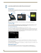
Modero X Series Touch Panels (10.1", 7"& 4.3") For information on the MXD/T-2000XL and MXD/T-1900L Panoramic X Series touch panels, refer to the Modero X-Series Panoramic Touch Panels Instruction Manual. Sleep Button X Series touch panels are operated using an integral touchscreen, as well as the Sleep button. For tabletop and landscape wall-mount panels, the Sleep button is located on the top center edge of the panel; for portrait panels it is located at the left center edge.(see FIG. 2).
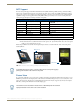
Modero X Series Touch Panels (10.1", 7"& 4.3") NFC Support X Series touch panels support Near Field Communications™ (NFC) Technology. NFC technology facilitates making transactions, exchanging digital content, and connecting electronic devices with a touch. NFC transmissions are shortrange (from a touch to a few centimeters), working with existing contact-less card technologies and containing built-in capabilities to support secure applications.
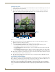
Modero X Series Touch Panels (10.1", 7"& 4.3") Starting Picture View 1. Connect a USB drive to the device. Picture View will automatically recognize all available images on the drive and start displaying them on the touchscreen. 2. When the images begin to display, touch any place on the touchscreen to open the configuration popup menu (FIG. 5). If no selection is made, this menu will remain in place for 15 seconds and then disappear. It may be accessed again by touching anywhere on the touchscreen.
Modero X Series Touch Panels (10.1", 7"& 4.3") Picture View Send Command (^PIC) The ^PIC Send Command stops either mode of Picture View, or starts Preview Mode. For more information, please refer to the Modero S Series Programming Guide, available at www.amx.com. All images must be in JPEG format. PNG and other image formats cannot be viewed through Picture View. Cleaning the Touch Overlay and Case When cleaning the device, do not directly spray the device with cleaning fluid.
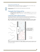
Modero X Series Touch Panels (10.1", 7"& 4.3") FIG. 7 Heat convection in rack-mounted devices Installation Recommendations During any installation, a lack of ventilation may produce conditions that may adversely affect the device’s operation. In these circumstances, special care must be made to make sure that temperatures within enclosed areas do not exceed the device’s maximum rated temperature.
MXT/D-1000 - 10.1" X Series Panels MXT/D-1000 - 10.1" X Series Panels MXT-1000 (Tabletop) The MXT-1000 10.1" Modero X Series® Tabletop Touch Panel (FG5968-03) features edge-to-edge capacitive touch glass with multi-touch capabilities. It features advanced technology empowering users to operate AV equipment seamlessly, while providing the ultimate in audio and video quality. The distinctive appearance will complement even the most sophisticated meeting facilities and homes.
MXT/D-1000 - 10.1" X Series Panels MXT-1000 Specifications (Cont.) TOUCH SCREEN DISPLAY • Display Type: TFT Active Matrix Color LCD with In-plane Switching Technology (IPS) • Display Size (WH): 9.9" x 6.7" (252 mm x 170 mm), 12.0" (304 mm) diagonal • Viewable Area (WH): 8.5" x 5.3" (217mm x 136mm), 10.
MXT/D-1000 - 10.1" X Series Panels MXT-1000 Specifications (Cont.
MXT/D-1000 - 10.1" X Series Panels MXT-1000 Installation Detailed specifications drawings for the MXT-1000 are available to download from www.amx.com. Top View Front View Side View Rear View FIG. 9 MXT-1000 Connector Locations USB peripherals (mouse, keyboard, etc.) may be connected to either of the two USB ports on the rear of the device (FIG. 10). Updates to the device’s firmware can also made via the USB ports (see Upgrading Firmware via USB Flash Drive on page 53 for details).
MXT/D-1000 - 10.1" X Series Panels Power via PoE Power for the MXT-1000 is supplied via PoE (Power Over Ethernet ), utilizing an AMX-certified, capacitive touchcompliant PoE injector such as the PS-POE-AT High Power PoE Injector (FG423-81) or other approved AMX PoE power source. The incoming Ethernet cable should be connected to the RJ45 port on the cable attached to the device. Ethernet Cable Installation and Modification In installations where concealing the Ethernet cable is desired, a hole at least 1.
MXT/D-1000 - 10.1" X Series Panels MXD-1000 (Wall-Mount - Landscape/Portrait) The MXD-1000 10.1" Modero X Series® Wall Mount Touch Panel features edge-to-edge capacitive touch glass with multi-touch capabilities as well as advanced technology empowering users to operate AV equipment seamlessly, while providing the ultimate in audio and video quality.
MXT/D-1000 - 10.1" X Series Panels MXD-1000 Specifications (Cont.) TOUCH SCREEN DISPLAY • Display Type: TFT Active Matrix Color LCD with In-plane Switching Technology (IPS) • Display Size (WH) Landscape: 9.9" x 6.7" (252 mm x 170 mm), 12.0" (304 mm) diagonal Portrait: 6.7" x 9.9" (170 mm x 252 mm), 12.0" (304 mm) diagonal • Viewable Area (WH) Landscape: 8.5" x 5.3" (217mm x 136mm), 10.1" (257mm) diagonal Portrait: 5.3" x 8.5" (136 mm x 217 mm), 10.
MXT/D-1000 - 10.1" X Series Panels MXD-1000 Specifications (Cont.) VIDEO • Supported Video Codecs, Landscape Model (FG5968-13): MPEG-2-TS: MPEG-2 Main Profile@High Level up to 720p at 25 fps (decode only) MPEG-2-TS: H.264 High Profile@Layer 4, AAC-LC up to 720p at 25 fps (encode/ decode) MJPEG up to 720p at 25 fps (decode only) • Supported Video Codecs, Portrait Model (FG5968-07): MPEG-2-TS: MPEG-2 Main Profile@High Level up to 720p at 25 fps (decode only) MPEG-2-TS: H.
MXT/D-1000 - 10.1" X Series Panels MXD-1000 Specifications (Cont.) ENVIRONMENTAL • Temperature (Operating): 32° F to 104° F (0° C to 40° C) • Temperature (Storage): 4° F to 140° F (-20° C to 60° C) • Humidity (Operating): 20% to 85% RH • Humidity (Storage): 5% to 85% RH • Power ("Heat") Dissipation: On: 21.3 BTU/hr Standby: 10.
MXT/D-1000 - 10.1" X Series Panels MXD-1000 Installation Detailed specifications drawings for the MXD-1000 are available to download from www.amx.com. Refer to A Note About Wall and Rack Installation on page 5 for important notes on thermal concerns with Rack and Wall installations. The MXD-1000 may be installed directly into a solid surface environment, using either solid surface screws or the included locking tabs for different mounting options.
MXT/D-1000 - 10.1" X Series Panels Backbox knockouts (X4) Locking tabs (X4) Backbox FIG. 14 MXD-1000 (Landscape) Note: Dimensions in parenthesis are in millimeters FIG. 15 MXD-1000 In order to ensure a stable installation of the MXD-1000, the thickness of the wall material must be a minimum of .50 inches (1.27cm) and a maximum of .875 inches (2.22cm). The mounting surface should also be smooth and flat.
MXT/D-1000 - 10.1" X Series Panels Installing the Backbox Note: Dimensions in parenthesis are in millimeters FIG. 16 MXD-1000 Installation Dimensions (front view) Note: Dimensions in parenthesis are in millimeters FIG. 17 MXD-1000 Installation Dimensions (side view) For best results, use the included Installation Template (68-5968-03) to ensure proper placement. Using the Installation Template to select the final placement of the Backbox is highly recommended.
MXT/D-1000 - 10.1" X Series Panels 9 7/8" (25.08cm) 8 3/4" (22.23cm) 6 3/4" (17.15cm) 5 1/2" (13.97 m) FIG. 18 10" Installation Template 1. Prepare the area by removing any screws or nails from the drywall before beginning the cutout process. 2. After ensuring proper placement, cut out the mounting surface for the Backbox, using the included Installation Template as a guide. Making sure the actual cutout opening is slightly smaller than the provided dimensions is highly recommended.
MXT/D-1000 - 10.1" X Series Panels 4X Installation Clamp for Wall Thickness .31 [12.0] to .98 [.25.0] 4X Knock-Outs Remove for Cable Routing as Needed #4 Screws FIG.
MXT/D-1000 - 10.1" X Series Panels 4X Installation Clamp for Wall Thickness .31 [12.0] to .98 [.25.0] 4X Knock-Outs Remove for Cable Routing as Needed #4 Screws FIG. 20 MXD-1000 Backbox Installation (Portrait) 4. Remove the Backbox knockouts (FIG. 19) and thread the incoming wiring through the knockout holes.
MXT/D-1000 - 10.1" X Series Panels The Backbox is clear to allow visual confirmation that the tabs have been extended and are gripping the wall, as well as in assisting with removal if necessary. For additional strength, #4 mounting screws (not included) may be secured through circular holes located at the left and right sides of the MXD-1000 (FIG. 19). In order to prevent damage to the touch panel, make sure that these are flush with the Backbox. 8.
MXT/D-1000 - 10.1" X Series Panels MXD-1000 (Landscape) Latch Hook Latch Hook Mounting Surface Backbox Snaps FIG. 22 Installing the MXD-1000 (Landscape) If a gap is observed between the panel and the Backbox, or feel any binding while locking down the panel, stop immediately and verify that no cables or other items are in the way. Do not force the panel into position, as this can cause damage to the touch screen or the panel electronics. 11.
MXT/D-1000 - 10.1" X Series Panels Removing the MXD-1000 The MXD-1000 is held in place via latch hooks and clips in the Backbox. In certain circumstances, such as firmware updates or other maintenance that requires accessing the device’s USB or Micro-USB ports, the device may need to be removed from the Backbox. The clips that lock down the MXD-1000’s bottom edge (Landscape) or right edge (Portrait) may be unlatched in order to remove the device from the mounting surface.
MXT/D-1000 - 10.1" X Series Panels Be careful not to pull on the cables or connectors. 6. To reattach the panel to its Backbox, repeat the installation procedure. For further information, refer to the video available at www.amx.com (go to Newsroom > Videos > Touch Panels).
MXT/D-1000 - 10.
MXT/D-700 - 7" X Series Panels MXT/D-700 - 7" X Series Panels MXT-700 (Tabletop) The MXT-700 7" Modero X Series® Tabletop Touch Panel (FG5968-04) features edge-to-edge capacitive touch glass with multi-touch capabilities, as well as advanced technology empowering users to operate AV equipment seamlessly, while providing the ultimate in audio and video quality. The distinctive appearance will complement even the most sophisticated meeting facilities and homes.
MXT/D-700 - 7" X Series Panels MXT-700 Specifications (Cont.) TOUCH SCREEN DISPLAY • Display Type: TFT Active Matrix Color LCD with Fringe Field Switching (FFS) - Wide Viewing Angle Technology • Display Size (WH): Landscape: 7.3" x 4.8" (186 mm x 122 mm), 8.8" (222 mm) diagonal • Viewable Area (WH): Landscape: 6.05" x 3.54" (154 mm x 90 mm), 7.0" (178 mm) diagonal • Resolution (WH): Landscape: 1024x600 • Aspect Ratio (WH): Landscape: 16:9 • Brightness: 400 cd/m2 • Contrast Ratio: 800:1 • Color Depth: 16.
MXT/D-700 - 7" X Series Panels MXT-700 Specifications (Cont.
MXT/D-700 - 7" X Series Panels MXT-700 Installation Detailed specifications drawings for the MXT-700 are available to download from www.amx.com. Top View Front View Side View Rear View FIG. 26 MXT-700 Connector Locations USB peripherals (mouse, keyboard, etc.) may be connected to either of the two USB ports on the rear of the device (FIG. 27). Updates to the device’s firmware can also made via the USB ports (see Upgrading Firmware via USB Flash Drive on page 53 for details).
MXT/D-700 - 7" X Series Panels Power via PoE Power for the MXT-700 is supplied via PoE (Power Over Ethernet ), utilizing an AMX-certified, capacitive touchcompliant PoE injector such as the PS-POE-AT High Power PoE Injector (FG423-81) or other approved AMX PoE power source. The incoming Ethernet cable connects to the RJ45 port on the cable attached to the device. Ethernet Cable Installation and Modification In installations where you wish to conceal the Ethernet cable, a hole at least 1.00” (2.
MXT/D-700 - 7" X Series Panels MXD-700 (Wall-Mount - Landscape/Portrait) The MXD-700 7" Modero X Series® Wall Mount Touch Panel features edge-to-edge capacitive touch glass with multitouch capabilities as well as advanced technology empowering users to operate AV equipment seamlessly, while providing the ultimate in audio and video quality. The MXD-700 is available in Portrait and Landscape layouts: .
MXT/D-700 - 7" X Series Panels MXD-700 Specifications (Cont.) TOUCH SCREEN DISPLAY • Display Type: TFT Active Matrix Color LCD with Fringe Field Switching (FFS) - Wide Viewing Angle Technology • Display Size (WH) Landscape: 7.3" x 4.8" (186 mm x 122 mm), 8.8" (222 mm) diagonal Portrait: 4.8" x 7.3" (122 mm x 186 mm), 8.8" (222 mm) diagonal • Viewable Area (WH) Landscape: 6.05" x 3.54" (154 mm x 90 mm), 7.0" (178 mm) diagonal Portrait: 3.54" x 6.05" (90 mm x 154 mm), 7.
MXT/D-700 - 7" X Series Panels MXD-700 Specifications (Cont.) AUDIO • Microphone: -42 dB ±3 dB sensitivity FET microphone • Speakers: 4 ohm, 2 Watt, 300 Hz cutoff frequency • Supported Audio Codecs: MP2 Layer I and II, MP3 (8 kHz, 11.025 kHz, 12 kHz, 16 kHz, 22.05 kHz, 24 kHz, 32 kHz, 44.1 kHz, 48 kHz) AAC-LC (8 kHz, 96 kHz) G.
MXT/D-700 - 7" X Series Panels The MXD-700-P-NC (FG5968-28) and MXD-700-L-NC (FG5968-29) No Comm touch panels do not have microphone capability. These otherwise have all of the functionality of the MXD-700 panels. Touch Panel Aspect Ratio While the touch panel screen physical dimensions fall between 16:9 and 16:10, any incoming video stream can be scaled to 16:9 if needed. This may lead to some letter boxing around the video in some cases.
MXT/D-700 - 7" X Series Panels Backbox knockouts (X4) Locking tabs (X2) Backbox FIG. 31 MXD-700 (Landscape) Note: Dimensions in parenthesis are in millimeters FIG.
MXT/D-700 - 7" X Series Panels In order to ensure a stable installation of the MXD-700, the thickness of the wall material must be a minimum of .50 inches (1.27cm) and a maximum of .875 inches (2.22cm). The mounting surface should also be smooth and flat. Installing the Backbox For best results, use the included Installation Template (68-5968-04) to ensure proper placement. Note: Dimensions in parenthesis are in millimeters FIG.
MXT/D-700 - 7" X Series Panels Using the Installation Template to select the final placement of the Backbox is highly recommended. The outside edges of the template are the same dimensions as the touch panel, which allows you to troubleshoot possible conflicts with wall edges, doors, and other potential obstacles. The Installation Template is marked on one side with directions for both landscape and portrait installations to ensure that the touch panel and Backbox are properly aligned. 1.
MXT/D-700 - 7" X Series Panels 4X Knock-Outs Remove for Cable Routing as Needed 2X Installation Clamp for Wall Thickness .37 [12.03] to .98 [.25.0] #4 Screws FIG. 36 MXD-700 Backbox Installation (Portrait) Leave enough slack in the wiring to accommodate any re-positioning of the panel. 4. Remove the Backbox knockouts and thread the incoming wiring through the knockout holes.
MXT/D-700 - 7" X Series Panels 8. Insert each connector into its corresponding location along the back of the device. To reach the RJ45 connector, gently pull it from beneath the electronics cover. Attach the Ethernet cable and gently push the connection back under the cover. To facilitate connection of the RJ45 connector to the Ethernet cable, press the RJ45’s cable into the RJ45 cable clip to hold it in a stable position.
MXT/D-700 - 7" X Series Panels Removing the MXD-700 The MXD-700 is held in place to the Backbox via latch hooks and clips on the Backbox, securing it to the mounting surface. In certain circumstances, such as firmware updates or other maintenance that requires accessing the device’s USB port, the device may need to be removed from the Backbox. The clips that lock down the MXD-700’s bottom edge (Landscape) or right edge (Portrait) may be unlatched in order to remove the device from the mounting surface.
MXT/D-700 - 7" X Series Panels 4. When the first side is free, repeat the process with the other. 5. With the edge of the touch panel free, carefully lift up and out (Landscape) or to the left and out (Portrait) to remove the touch panel from the Backbox. Be careful not to pull on the cables or connectors. 6. To reattach the panel to its Backbox, repeat the installation procedure. For further information, refer to the video available at www.amx.com (go to Newsroom > Videos > Touch Panels).
MXD-430 4.3” X Series Wall/Flush Mount Touch Panel MXD-430 4.3” X Series Wall/Flush Mount Touch Panel Overview The MXD-430 4.3” Modero X Series Wall/Flush Mount Touch Panel (FG5968-15) features edge-to-edge capacitive touch glass with multi-touch capabilities as well as advanced technology empowering users to operate AV equipment seamlessly while providing the ultimate in audio and video quality. The distinctive appearance will complement even the most sophisticated meeting facilities and homes.
MXD-430 4.3” X Series Wall/Flush Mount Touch Panel MXD-430 Specifications (Cont.) CERTIFICATIONS • UL 60950-1 • FCC Part 15 Class B • C-Tick CISPR 22 Class B • CE EN 55022, EN 55024 and EN 60950-1 • IEC 60950-1 • IC • IEC/EN-60950 • RoHS / WEEE compliant TOUCH SCREEN DISPLAY • Display Type: TFT Active Matrix Color LCD with In-plane Switching Technology (IPS) • Display Size (WH): Portrait: 3.3" x 4.8" (82 mm x 120 mm), 4.9" (119 mm) diagonal • Viewable Area (WH): Portrait: 2.2" x 3.7" (56 mm x 94 mm), 4.
MXD-430 4.3” X Series Wall/Flush Mount Touch Panel MXD-430 Specifications (Cont.
MXD-430 4.3” X Series Wall/Flush Mount Touch Panel MXD-430 Installation Refer to A Note About Wall and Rack Installation on page 5 for important notes on thermal concerns with Wall and Rack Installations. The MXD-430 may be installed directly into a solid surface environment, using either solid surface screws or the included locking tabs for different mounting options. Once installed, the MXD-430 is contained within a clear outer housing known as the Backbox (FIG. 41).
MXD-430 4.3” X Series Wall/Flush Mount Touch Panel Installing the MXD-430 into a Wall The MXD-430 comes with a clear plastic backbox (designed to attach the panel to most standard wall materials. This backbox has two locking tabs (one on each side) to help lock the backbox to the wall. These locking tabs are only extended AFTER the backbox is inserted into the wall. (FIG. 42). Backbox Locking tab Locking tab MXD-430 (front) Backbox knockout FIG.
MXD-430 4.3” X Series Wall/Flush Mount Touch Panel Using the included template to select the final placement of the Backbox is highly recommended. The outside edges of the template are the same dimensions as the touch panel, which allows you to troubleshoot possible conflicts with wall edges, doors, and other potential obstacles. 3. After ensuring proper placement, cut out the mounting surface for the Backbox using the MXD-430 Installation Template as a guide.
MXD-430 4.3” X Series Wall/Flush Mount Touch Panel Apply enough pressure to the screw head to keep the box flush with the wall: this ensures that the locking tabs will tighten up against the inside of the wall. The Backbox is clear to allow visual confirmation that the tabs have been extended and are gripping the wall, as well as in assisting with removal if necessary.
MXD-430 4.3” X Series Wall/Flush Mount Touch Panel Snap Backbox Mounting Surface Latch Hooks FIG. 46 Installing the MXD-430 If you see a gap between the panel and the Backbox or feel any binding while locking down the panel, stop immediately and verify that no cables or other items are in the way. Do not force the panel into position, as this can cause damage to the touch screen or the panel electronics. 11.
MXD-430 4.3” X Series Wall/Flush Mount Touch Panel Uninstalling the MXD-430 The MXD-430 is held in place to the Backbox via latch hooks and a clip on the Backbox (FIG. 46), securing it to the mounting surface. In certain circumstances, such as firmware updates or other maintenance that requires accessing the device’s USB port, the device may need to be removed from the Backbox. The clip that locks down the MXD-430’s top edge may be unlatched in order to remove the device from the mounting surface.
MXD-430 4.3” X Series Wall/Flush Mount Touch Panel 3. With a stout, strong point (a push pin or straightened paper-clip, for example), carefully press straight into the access holes in the center of the molding (FIG. 48) until the snap is disconnected. Grasp the top of the panel and pull gently outward until the side of the panel is free of the snap. Use your other hand to stabilize the front of the touch panel. Always pull on the frame of the touch panel. NEVER pull on the glass edge. 4.
Upgrading Firmware Upgrading Firmware Overview Programming the X Series touch panels require the use of NetLinx Studio and TPDesign4, both available from www.amx.com. Downloading Firmware Updates From www.amx.com Before attempting to upgrade the firmware, you must have the appropriate Kit file for your touch panel: All X Series touch panels share the same firmware. 1. Open the product page for the panel, at www.amx.com (Trade Site). 2.
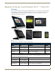
Upgrading Firmware Directory Names for Firmware Files - by Touch Panel Type Directory Name Panel Type(s) "MXT-1000" MXT-1000 (FG5968-03) MXT-1000-NC (FG5968-24) "MXD-1000" MXD-1000-P (FG5968-07) MXD-1000-P-NC (FG5968-25) MXD-1000-L (FG5968-13) MXD-1000-L-NC (FG5968-26) "MXT-700" MXT-700 (FG5968-04) MXT-700-NC (FG5968-27) "MXD-700" MXD-700-P (FG5968-08) MXD-700-P-NC (FG5968-28) MXD-700-L (FG5968-14) MXD-700-L-NC (FG5968-29) "MXD-430" MXD-430-P (FG5968-15) 3. Copy the firmware (.
Upgrading Firmware Upgrading from Previous Firmware X Series panels provide the option to revert the device to the previous firmware run before an upgrade. To upgrade the device from previously loaded firmware: 1. From the Settings page, select the Configuration page. 2. From the Configuration page, select Admin. 3. From the Admin Configuration page, select Install Firmware. 4. In the Firmware Installation page, select Previous. 5. The Confirmation Dialog box (FIG.
Upgrading Firmware Transferring the KIT File via NetLinx Studio 1. In Netlinx Studio, right-click in the Online Tree tab of the Workspace window and select Refresh System Online Tree to refresh the device listing. The touch panel should be indicated in the device list. 2. Right-click on the target panel and select Firmware Transfer to open the Send to NetLinx Device dialog. Alternatively, select Tools > Firmware Transfers > Send To NetLinx Device to open this dialog (FIG. 54): FIG.
Appendix: Troubleshooting Appendix: Troubleshooting Overview This section describes the solutions to possible hardware/firmware issues that could arise during the common operation of a Modero X Series touch panel. Panel Doesn’t Respond to Touches Symptom: The device either does not respond to touches on the touch screen or does not register the touch as being in the correct area of the screen. If the screen is off: The device may be in Display Sleep Mode.
8/14 ©2014 AMX. All rights reserved. AMX and the AMX logo are registered trademarks of AMX. AMX reserves the right to alter specifications without notice at any time. It’s Your World - Take Control™ 3000 RESEARCH DRIVE, RICHARDSON, TX 75082 USA • 800.222.0193 • 469.624.8000 • 469-624-7153 fax • 800.932.6993 technical support • www.amx.