
Instruction manual


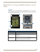

MXT/D-700 - 7" X Series Panels
40
MXD/T-1000, MXD/T-700 and MXD-430 Modero X Series® Touch Panels
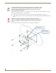
8. Insert each connector into its corresponding location along the back of the device.
To reach the RJ45 connector, gently pull it from beneath the electronics cover.
Attach the Ethernet cable and gently push the connection back under the cover.
9. Test the incoming wiring by attaching the panel connections to their terminal locations and applying power.
Verify that the panel is receiving power and functioning properly to prevent repetition of the installation.
Remove power before continuing with the installation.
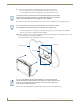
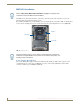
10. Latch the panel onto the top hooks on the Backbox and push it down (Landscape) onto the bottom snaps or on the
left side and push it to the right (Portrait) (FIG. 37).
Press gently but firmly on the ends until the snaps “click” to lock it down.
11. Reconnect the terminal Ethernet and USB to their respective locations on the Ethernet port.
To facilitate connection of the RJ45 connector to the Ethernet cable, press the RJ45’s
cable into the RJ45 cable clip to hold it in a stable position. Make sure to remove the
cable from the cable clip before continuing the rest of the installation.
Do not disconnect the connectors from the touch panel. The unit must be installed
with the attached connectors before being inserted into the mounting surface.
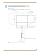
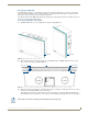
FIG. 37 Installing the MXD-700
Mounting Surface
Backbox
Latch Hooks
Snaps
If you see a gap between the panel and the Backbox, or feel any binding while
locking down the panel, stop immediately and verify that no cables or other items are
in the way. Do not force the panel into position, as this can cause damage to the
touch screen or the panel electronics.