Operation/Reference Guide Mio Modero ® Device Family Control System Accessories Last Revised: 12/16/2009
AMX Limited Warranty and Disclaimer AMX warrants its products to be free of defects in material and workmanship under normal use for three (3) years from the date of purchase from AMX, with the following exceptions: • Electroluminescent and LCD Control Panels are warranted for three (3) years, except for the display and touch overlay components that are warranted for a period of one (1) year.
Table of Contents Table of Contents Overview ............................................................................................................1 Specifications............................................................................................................ 1 Available Color Schemes ................................................................................................. 2 Mio Modero LCD Feature ...................................................................................
Table of Contents ^GLY ......................................................................................................................................... 19 ^JST- ......................................................................................................................................... 19 ^PRX- ........................................................................................................................................ 20 ^SHO .................................................
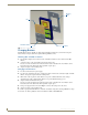
Overview Overview The Mio Modero device family provides a wide range of control capabilities in the form of keypads that are as adept as they are elegant. Each device is available as single style (8 button max) or double style (16 button max) with an optional LCD capped button (FIG. 1). FIG.
Overview Specifications (Cont.) Weight (range): .25 lbs (.11 kg) - .50 lbs (.23 kg) Operating Environment: • Operating Temperature: 0° to 50° C (32° to 122° F) Mounting: Mounts into US and a majority of International single gang back boxes.
Overview Mio Modero LCD Feature The Mio Modero Elite is available with an optional LCD screen. The LCD is a scalable black-and-white image (SPI) controlled 96 x 96 resolution monochrome FSTN display with a white Electroluminescent back light. The viewable area of the screen is 25 mm x 25 mm. The LCD displays an 18 pt. font and supports 4 lines of text. The viewing angle of the LCD is 12 o’clock, allowing for a top down viewing once mounted to a wall.
Overview 4 Mio Modero Device Family
Installation Installation Before touching the device, discharge the static electricity from your body by touching a grounded metal object. The basic front and rear components of the Mio Modero are as follows: Installation Button AxLink 3.5 mini Phoenix connector Slot to pry button free PWR+ Screw holes 8 position mini DIP switch Notch to pry faceplate free (Rear Single) (Front Single) 8 position mini DIP switch AxLink 3.
Installation Mounting Frame LCD Installation Buttons Faceplate FIG. 3 Sections of The Mio Modero Changing Buttons The Mio Modero Classic and Elite are shipped with "installation" buttons; they are intended to be place holders until your engraved buttons, designed with KeypadBuilder, arrive. Switching Out "Installation" Buttons 1. Pry the button using the slot on the front of the "installation" buttons to remove them from the Mio Modero. 2.
Installation Mio Modero Prestige The Mio Modero Prestige ships with sheets of common menu items and icons for creating inserts for single and double buttons. 1. If connected, disconnect the power supply. 2. If connected to mounting frame, place a flathead screwdriver in the notch at the bottom right of the Mio Modero, and pry the faceplate from the mounting frame. 3. On the back of the faceplate locate the button access points, outlined with white circles.
Installation If you later change the device number, remove and reconnect the AxLink power connector to enter the new device number into memory. AMX has created Dip Switch2 to assist in calculating dip switch position values. Download the program Dip Switch2 from www.amx.com for free. Wiring The Mio Modero uses a four-pin mini AxLink connector for power and data. Do not connect power to the Mio Modero until the wiring is complete.
Installation AxLink Data and Power Connections Connect the control system's AxLink connector to the AxLink connector on the rear panel of the Mio Modero for data and 12 VDC power as shown in FIG. 6. PWR + PWR + AXP AXP AXM AXM GND - GND Mio Modero Control System FIG. 6 AxLink straight-thru wiring Using AxLink For Data With an Auxiliary Power Supply Connect the controller’s AxLink connector to the AxLink connector on the rear panel of the Mio Modero device, as shown in FIG. 7.
Installation Mounting Procedures FIG. 8 shows the wallbox mounting dimensions for the single and double style Mio Modero. AMX recommends mounting the Mio Modero in a standard one-gang wallbox, a conduit box per NEC specs section 370, with a minimum internal clearance of 2-5/8" x 1-3/4" x 1-5/8" (HWD), but it is possible to mount the Mio Modero to a podium without a wallbox. 2.000 [50.8 MM] 3.282 [83.4 MM] 2.250 [57.2 MM] FIG. 8 Mio Modero Single Style mounting dimensions 2.000 [50.8 MM] 3.282 [83.
Installation Do not overtighten the screws when mounting the mounting frame. The device should be flush with mounting surface. 6. Attach the faceplate to the mounting frame first at the top and swing it to the bottom. See FIG. 10. FIG. 10 Attaching the faceplate to the mounting frame Podium Mounting 1. Use the cutout dimension shown in either FIG. 8 or FIG. 9 to cutout the mounting frame install surface 2. 3. 4. 5. for the Mio Modero.
Installation Accent Frame While the Mio Modero device family does fit into many International wallboxes, it may be necessary to utilize the optional accent frame to completely cover the wallbox. To install the Mio Modero with the optional accent frame: 1. Use the cutout dimension for the wallbox to cut out the install surface for the Mio Modero. 2. Place the accent frame on the wallbox; align the screw holes with the mounting holes on the wallplate. Fasten the wallplate to the wallbox.
Mio Modero IR Mio Modero IR The Mio Modero IR (FIG. 11) is a remote IR receiver for use with NetLinx® Central Controllers and operates via the AxLink bus to remotely control devices. The Mio Modero IR is in a wall panel that fits into the US-style single-gang enclosure and most International single-gang enclosures. The Mio Modero IR works with AMX 38 kHz and 455 kHz IR transmitters. Faceplate IR Cover Mounting Frame FIG.
Mio Modero IR Wiring and Installation Set the receive AxLink device number before installing the Mio Modero IR. FIG. 12 illustrates the location of key components on the Mio Modero IR circuit board. AxLink 3.5 mini Phoenix connector PWR+ Screw holes 8 position mini DIP switch Notch to pry faceplate free (Rear Single) FIG. 12 Location of key components on the Mio Modero IR circuit board Setting the AxLink Device Number 1. If connected, disconnect the power supply. 2.
Mio Modero IR AxLink Data and Power Connections The Mio Modero IR uses a four-pin mini AxLink connector for power and data. Connect the control system's AxLink connector to the AxLink connector on the rear panel of the Mio Modero IR for data and 12 VDC power as shown in FIG. 14. PWR + PWR + AXP AXP AXM AXM GND - GND - Mio Modero Control System FIG. 14 AxLink straight-thru wiring For wire prepartaion guidelines, refer to Preparing captive wires section on page 8.
Mio Modero IR 1. Use the cutout dimension for the wallbox to cutout the install surface for the Mio Modero IR. 2. Confirm that the terminal end of the AxLink cable is disconnected, and not receiving power. 3. If the faceplate is connected to the mounting frame, place a flathead screwdriver in the notch at the bottom right of the Mio Modero IR, and pry the faceplate from the mounting frame. 4. Connect the AxLink power supply.
Programming The Mio Modero Programming The Mio Modero KeypadBuilder Most functionality of the Mio Modero is handled using the application, KeypadBuilder. Go to www.amx.com for the KeypadBuilder Instruction Manual. There are a select number of SEND_COMMANDs the Mio Modero recognizes. SEND_COMMANDs Below is a list of SEND_COMMANDs accepted by the Mio Modero device family from NetLinx masters. As indicated, not every command applies to all Mio Modero devices, e.g.
Programming The Mio Modero SEND_COMMANDs (Cont.) ^CFG Set Keypad to Combine Mode. Combine mode allows yu to combine/uncombine adjacent buttons on the Keypad. Syntax: "'^CFG- '" Variables: • command value = (1= enter combine mode, 0= exit combine mode). Example: SEND_COMMAND Panel,"'^CFG-1'" Sets the Keypad to button combine mode. Note: While in button combine mode, no pushes will be sent.
Programming The Mio Modero SEND_COMMANDs (Cont.) ^FML D L Sets a line of the display to a dynamic line with a level Syntax: "'^FML-,D,L'" Variables: • variable text address range = 1 - 4; the address range corresponds to the dynamic line number.
Programming The Mio Modero SEND_COMMANDs (Cont.) ^PRX- Sets the sensitivity for the proximity sensor. Syntax: "'^PRX-#'" Variable: • # = a value from 0 - 31. Example: SEND_COMMAND Panel,"'^PRX-15'" Sets the proximity sensor for the device to a level of approximately 50%. ^SHO Show or hide text with a set variable text range. Syntax: "'^SHO-,'" Variables: • variable text address range = 1 - 4; the address range corresponds to the dynamic line number.
Programming The Mio Modero SEND_COMMANDs (Cont.) @SWK Sends a string to the master upon wake up. Syntax: "'@SWK-'" Variable: • new text = 1 - 20 ASCII characters. Default string is WAKEUP. Example: SEND_COMMAND Panel,"'@SWK-Wake KeyPad" Sends the string " Wake KeyPad " to the master at time of wake up. Assign a text string to those LCD buttons with a defined address range. Sets non (LCD equipped only) unicode text.
Programming The Mio Modero Combining Buttons Use the ^CFG Send Command (see page 18) to combine/uncombine adjacent buttons on the Keypad: The variables for the ^CFG command value are: 1= enter combine mode, 0= exit combine mode. 1. Send the following Send Command to the Keypad, to set the Keypad to button combine mode: SEND_COMMAND Panel,"'^CFG-1'" While in button combine mode, no pushes will be sent. 2. Hold down two adjacent buttons for 2 seconds. 3.
Programming The Mio Modero Mio Modero Device Family 23
AMX. All rights reserved. AMX and the AMX logo are registered trademarks of AMX. AMX reserves the right to alter specifications without notice at any time. ©2009 12/09 It’s Your World - Take Control™ 3000 RESEARCH DRIVE, RICHARDSON, TX 75082 USA • 800.222.0193 • 469.624.8000 • 469-624-7153 fax • 800.932.6993 technical support • www.amx.