
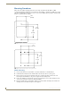
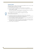
Specifications
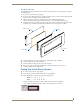
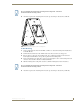

Installation
9
Mio Modero Device Family
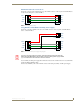
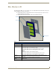
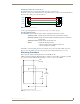
AxLink Data and Power Connections
Connect the control system's AxLink connector to the AxLink connector on the rear panel of the Mio Modero
for data and 12 VDC power as shown in FIG. 6.
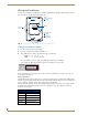
Using AxLink For Data With an Auxiliary Power Supply
Connect the controller’s AxLink connector to the AxLink connector on the rear panel of the Mio Modero
device, as shown in FIG. 7.
Use an auxiliary 12 VDC power supply when the distance between the controller and server exceeds the limits
described in Wiring Guidelines table.
Connect only the GND (-) wire on the AxLink connector when using an auxiliary 12 VDC power supply.
FIG. 6 AxLink straight-thru wiring
FIG. 7 AxLink and 12 VDC power supply wiring diagram
PWR +
AXP
AXM
GND -
PWR +
AXP
AXM
GND -
Mio Modero Control System
PWR +
AXP
AXM
GND -
PWR +
AXP
AXM
GND -
Mio Modero Control System
12VDC Power Supply
PWR +
GND -
If you are not using power from AxLink, disconnect the wiring from the controller
before wiring the Mio Modero device. Make sure the auxiliary power supply’s PWR
(+) is not connected to the controller’s AxLink connector.