Operation/Reference Guide Modero® NXD-500i G4 Touch Panel 5" Wall/Flush Mount Touch Panel with Intercom Touch Panels Initial Release: 11/3/2008
AMX Limited Warranty and Disclaimer AMX warrants its products to be free of defects in material and workmanship under normal use for three (3) years from the date of purchase from AMX, with the following exceptions: • Electroluminescent and LCD Control Panels are warranted for three (3) years, except for the display and touch overlay components that are warranted for a period of one (1) year.
Table of Contents Table of Contents Introduction ........................................................................................................1 NXD-500i Specifications ........................................................................................... 3 Front Bezel Button.................................................................................................... 5 Ethernet and mini-USB Ports ....................................................................................
Table of Contents Master Connection section - NetLinx Master Ethernet IP Address - Auto Mode........... 36 Using G4 Web Control to Interact with a G4 Panel ................................................ 37 Using the NetLinx Master to control the G4 panel ................................................. 38 Upgrading Modero Firmware ...........................................................................43 Upgrading the Firmware via the USB port........................................................
Table of Contents Refreshing the Panel Statistics ...................................................................................... 73 Clearing the Panel Statistics.......................................................................................... 73 Connection Utility Page ................................................................................................ 74 Using the Connection Utility .........................................................................................
Table of Contents iv NXD-500i 5" Wall/Flush Mount Touch Panel with Intercom
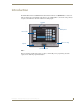
Introduction Introduction The NXD-500i 5" Modero Wall/Flush Mount Touch Panel with Intercom (FG2261-02) is a widescreen full-color mini-touch panel with full sound and intercom capability (FIG. 1). It offers the same perimeter footprint as the NXD-CV5, but with a shallower mounting depth. Faceplate Microphone Touch screen Button Trim Ring Speaker Front Bezel button FIG.
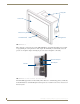
Introduction Locking tabs Touch screen Button trim ring Front Bezel button Back box FIG. 2 NXD-500i Color Video Touch Panel - Schematics FIG. 3 shows the connectors located on the NXD-500i Modero panel. The mini-USB port is used both for programming the touch panel and for audio output. The mini-USB port automatically detects the presence of a headphone adaptor, allowing the port to be used for headphone connectivity. Ethernet 10/100 port Mini-USB port Back box FIG.
Introduction Key features include: Support of AMX's 4th generation (G4) graphics which provide higher brightness, richer colors, and deeper contrast. The new G4 graphics technology is supported by the TPDesign4 Touch Panel Design application, available for download from www.amx.com. Display of images on a large 16:9 image format, while providing a wide 90-degree top-tobottom viewing angle. A front panel light sensor, motion sensor, IR receiver and a Sleep/Setup Access button.
Introduction Specifications for NCXC-500i 5" Widescreen Video Touch Panel (Cont.) Supported Audio Sample Rates: • 48000Hz, 44100Hz, 32000Hz, 24000Hz, 22050Hz, 16000Hz, 12000Hz, 11025Hz, and 8000Hz. Intercom: • Full duplex VoIP capabilities. Front Panel Components: Light sensor: • Motion-sensitive light detector for automatic adjustment of the panel brightness (a dim room results in a dimmer LCD display, and a bright room results in a brighter LCD display).
Introduction Specifications for NCXC-500i 5" Widescreen Video Touch Panel (Cont.
Introduction 6 NXD-500i 5" Wall/Flush Mount Touch Panel with Intercom
Installation Installation While the NXD-500i is designed to fit into pre-existing NXD-CV5 touch panel sites, the actual installation differs from that of the NXD-CV5 is several significant ways. The NXD-500i can be installed either directly into the (optional) CB-TP5i Rough-In Box or another solid surface environment, using either solid surface screws or the included locking tabs for different mounting options. For more information, please refer to the NXD-500i User Manual, available at www.amx.com.
Installation Removing the Faceplate In certain circumstances, the Faceplate must be removed and replaced with a new faceplate. Because the device is installed against a wall, the faceplate must be removed carefully to prevent the two top prongs on the underside of the Faceplate from being broken. To remove the faceplate: 1. Gently lift up on the faceplate from the bottom. Do NOT pull up from the sides or the top. 2.
Installation Installation of an NXD-500i Touch Panel The NXD-500i can be installed either directly into the (optional) CB-TP5i Rough-In Box or other solid surface environment, using solid surface screws or the included locking tabs as mounting options. The following sections describe mounting the touch panel directly into a pre-wall rough-in box, a solid surface, drywall, or an NXA-RK5 Rack Mount Kit.
Installation 5. Install the drywall/sheetrock before inserting the main NXD-500i device into the CB-TP5i. Installing the NXD-500i panel within a Rough-In Box The Rough-In Box must be mounted prior to continuing this section. Refer to the procedures in the Pre-Wall Installation of the Rough-In Box section on page 9 for detailed pre-wall installation instructions.
Installation with the wall: this ensures that the locking tabs will tighten up against the inside of the wall. The back box is clear to allow visual confirmation that the tabs have been extended and are gripping the wall. This also allows visual confirmation if the entire assembly has to be removed from the wall for any reason. The maximum recommended torque to screw in the locking tabs on the back box is 105 IN-OZ [74 N-CM].
Installation Installing the NXD-500i into drywall Unlike most AMX touchpanels, the NXD-500i comes with a clear plastic backbox (FIG. 7) designed to attach the panel to standard drywall. This backbox has a locking tab on three of the four faces (missing only on the face containing the space for the connections) to help lock the backbox to the wall. These locking tabs are only extended AFTER the backbox is inserted into the wall. Locking tab screws Locking tabs - Closed Locking tabs - Open FIG.
Installation FIG. 8 NXD-500i Wall Mount panel dimensions Making sure that the actual cutout opening be slightly smaller than the provided dimensions is highly recommended. This action provides the installer with a margin for error if the opening needs to be expanded. Too little drywall removed is always better than too much. 3. Remove the Faceplate/bezel (A in FIG. 9) from the main NXD-500i device (B in FIG. 9) by gripping the faceplate and pulling up and then out with gentle outward force. 4.
Installation Do not disconnect the connectors from the touch panel. The unit must be installed with the attached connectors before being inserted into the drywall. 7. Push the back box into the wall opening. Insure that the locking tabs lie flush against the back box. 8. Extend the locking tabs on the sides of the back box by tightening the screws inside the box. Not all of the tabs must be extended to lock the back box in place, but extending a minimum of the top and bottom tabs is highly recommended.
Installation Installing the NXD-500i into a Flat Surface using #4 screws Three #4 mounting screws (not included) are secured through circular holes located at the left and right sides of the NXD-500i. The most important thing to remember when mounting the NXD-500i is that the back box must be installed flush against the mounting surface. Refer to SP-2261-02 for detailed installation dimensions (reproduced in FIG. 10).
Installation The USB connectors can be from either a USB extension cable or a wireless USB RF transmitter. 6. Test the incoming wiring by connecting the panel connections to their terminal locations. Verify that the panel is receiving power and functioning properly before finalizing the installation. Attachment is done along the edges of the cutout Flat installation surface Install the three #4 Mounting Screws (not included) into these three holes (suggested length of screws is 0.
Installation Installing an NXD-500i into a Rack Mount Kit (NXA-RK5) The NXA-RK5 is a 19" (48.26 cm) wide metal rack-mount (with black matte finish) measuring 3 rack units high. 1. Remove the Faceplate/Trim Ring assembly from the main NXD-500i unit. 2. Thread the incoming Ethernet and USB wiring from their terminal sources through the surface opening, leaving enough slack in the wiring to accommodate any re-positioning of the panel. 3.
Installation Wiring Guidelines for the NXD-500i Panel The NXD-500i panel utilizes the Power over Ethernet protocol, where it draws power directly from its Ethernet connection. Because of this, the panel has no need for standard power inputs or outputs. Ethernet/RJ-45 Port: Connections and Wiring FIG. 12 describes the blink activity for the Ethernet 10/100 Base-T RJ-45 connector and cable. The Ethernet cable is connected to the side of the Wall Mount panels.
NXD-500i Touch Panel Accessories NXD-500i Touch Panel Accessories The following section outlines and describes both the included accessories and other AMX equipment available for the NXD-500i. PS-POE-AF PoE Injector The PS-POE-AF PoE Injector (FG423-80) is a single-port, self-contained Power-over-Ethernet (PoE) power supply that delivers both DC power and data to PoE-equipped devices by “injecting” DC power through a Cat5 Ethernet cable (FIG. 14).
NXD-500i Touch Panel Accessories PS-POE-AF Specifications (Cont.) General Specifications Topology • Switching-Fixed • Frequency Flyback Dielectric Withstand • Primary-Secondary 3000VAC, 4250VDC • Secondary-Ground 500VDC Spacing 5mm Primary-Secondary Leakage Current Less than 250 uA Efficiency • 65% Typical @ Max. Load Weight (excluding cord) 7 Ounces (200 Grams) • and 120VAC/60 Hz Dimension • 5.24L x 2.13W x 1.42H (in) • 133.0L x 54.0W x 36.
Panel Calibration Panel Calibration This section outlines the steps for calibrating the touch panel. Calibrating the panel before its initial use and after completing a firmware download is highly recommended. Modero panels are set up in the factory with specific demo touch panel pages. The first splash screen that appears indicates the panel is receiving power, beginning to load firmware, and preparing to display the default touch panel pages.
Panel Calibration If the calibration was improperly set and you cannot return to the Calibration page through the panel’s firmware, this firmware page may be accessed via G4 WebControl, where you can navigate to the Protected Setup page and press the Calibrate button through a VNC window. This action causes the panel to go to the Calibration page seen above, where the actual touch panel may be physically calibrated again using the above procedures.
Configuring Communication Configuring Communication Communication between the Modero panel and the Master is done using either USB or ETHERNET (DHCP or Static IP). Ethernet communication can only be achieved via a direct Ethernet connection. Before commencing, verify that you are using the latest NetLinx Master and Modero panel firmware, and also verify you are using the latest versions of AMX’s NetLinx Studio and TPDesign4 applications. These are available at www.amx.com.
Configuring Communication Before continuing, open NetLinx Studio. This program assists in developing a System Number, Master IP/URL, and Master Port number. Refer to the NetLinx Master’s instruction manual for more information. 8. Obtain the System Number and Master IP Address from NetLinx Studio. This information must be specific for the system used with the configured Modero panel. 9. Press the Front Setup Access button for 4 seconds to open the Setup page. 10.
Configuring Communication Configuring and Using USB with a Virtual Master NetLinx Studio can be set up to run a Virtual Master where the PC acts as the Master by supplying its own IP Address for communication to the panel. The PC is first equipped with the USB driver, the panel is then configured for USB communication, and then Studio is configured to act as the Master.
Configuring Communication 5. Toggle the blue Type field (from the Master Connection section) until the choice cycles to USB. Refer to the System Settings Page section on page 59 for more information about the fields on this page. ALL fields are then greyed-out and read-only, but still display any previous network information. 6. Press the Back button on the touch panel to return to the Protected Setup page. 7. Press the on-screen Reboot button both to save any changes and restart the panel.
Configuring Communication Step 3: Confirm and View the current AMX USB device connections The USB driver information can be confirmed via two different methods: Via the Control panel (previous steps 1 and 2) or Via the Unplug or Eject Hardware icon from the Taskbar. 1. Navigate to Start > Settings > Control Panel > and double-click the System icon to launch the System Properties dialog. 2. Select the Hardware tab and click on the Device Manager button to launch the Device Manager dialog.
Configuring Communication USB detection icon FIG. 21 USB Properties windows If a yellow exclamation point appears next to the AMX USB LAN LINK device (within the hardware devices section of the Unplug or Eject Hardware window), stop and close the USB operation. Reconnect the USB cable to the panel and repeat the setup procedures. Refer to the Troubleshooting section on page 131 for more detailed information.
Configuring Communication IP Address of computer (not needed as this is a direct USB connection) FIG. 22 Assigning Communication Settings for a Virtual Master 6. Click on the Virtual Master radio box from the Transport Connection Option section to configure the PC to communicate directly with a panel. Everything else, such as the Authentication, is greyed out because this action is not going through the Master’s UI. 7.
Configuring Communication A mini-USB connection is only detected after it is installed onto an active panel. Connection to a previously powered panel which then reboots, allows the PC to detect the panel and assign an appropriate USB driver. 1. Verify this direct USB connection (Type-A on the panel to mini-USB on the panel) is configured properly using the steps outlined in the previous two sections. 2.
Configuring Communication Configuring a Wired Ethernet Connection It is necessary to tell the panel as to which Master it should be communicating. This "pointing to a Master" is done via the System Settings page, where the IP Address, System Number and Username/ Password information assigned to the target Master is configured. Until those parameters are configured, your Connection Status icon will remain red, indicating that it has no current connection to a Master.
Configuring Communication Check with your System Administrator for a pre-reserved Static IP Address assigned to the panel. This address must be obtained before Static assignment of the panel continues. 3. Toggle the DHCP/Static field (from the IP Settings section) until the choice cycles to Static. 4. Press the IP Address field to open a Keyboard and enter the Static IP Address provided by your System Administrator. 5. Press Done after you are finished entering the IP information. 6.
Configuring Communication Before commencing, verify that the NetLinx Master is using the latest available version of its firmware. 2. Verify that the NetLinx Master is receiving power and is communicating via an Ethernet connection with the PC running NetLinx Studio. 3. Verify that the green Ethernet LED on the rear Ethernet port on the Master is illuminated, indicating a proper connection. 4.
Configuring Communication Enter this IP into the Master IP/URL field on the System Settings page IP Addresses of computer (also obtained by using the Start > Run > cmd command) FIG. 25 Assigning Communication Settings and TCP/IP Settings for a Virtual Master 6. Click on the Virtual Master radio box from the Transport Connection Option section to indicate you are wanting to configure the PC to communicate with a panel. All other fields will be greyed out because the Master’s UI is not being used. 7.
Configuring Communication The System Number is assigned to the Master within the AMX software application (these must match) Enter the IP Address information of the PC used as a Virtual Master When using a Virtual Master, there is no need to enter a username and/or password FIG. 26 Sample System Connection page (for Virtual Master communication) 17. Click Done to accept the new value and return to the System Connection page. 18. Do not alter the Master Port Number value.
Configuring Communication Master Connection section - NetLinx Master Ethernet IP Address - Listen Mode In this mode, add the Modero panel IP Address into the URL List of the Master by using NetLinx Studio. This mode sets the Modero panel to "listen" for broadcasts from the Master (using the panel IP from its URL list). 1. Obtain either a Static IP for the Modero panel (from your System Administrator) or a DHCP Address from the IP Settings of the System Connection page.
Configuring Communication The NetLinx Master and the Modero panel must both be on the same Subnet. Using G4 Web Control to Interact with a G4 Panel The G4 Web Control feature allows a PC to interact with a G4-enabled panel via the web. This feature works in tandem with the new browser-capable NetLinx Security firmware update (build 300 or higher). G4 Web Control is only available with the latest Modero panel firmware.
Configuring Communication 7. Press the Web Control Name field to open the Web Name keyboard. 8. From the Web Name keyboard, enter a unique alphanumeric string to identify this panel and press Done when finished. This information is used by the NetLinx Security Web Server to display onscreen links to the panel. The on-screen links use the IP Address of the panel and not the name for communication (FIG. 28). FIG. 28 Sample relationship between G4 Web Control and Mange WebControl Connections window 9.
Configuring Communication 1. Launch your web browser. 2. Enter the IP Address of the target Master (ex: http://198.198.99.99) into the web browser’s Address field. 3. Press the Enter key on your keyboard to begin the communication process between the target Master and your computer. Initially, the Master Security option is disabled from within the System Security page, and no username and password is required for access or configuration.
Configuring Communication FIG. 30 Web Control VNC installation and Password entry screens The G4 Web Control application is sent by the panel to the computer that is used for communication. Once the application is installed, this popup will no longer appear. This popup will only appear if connecting to the target panel using a different computer. 8. In some cases, a Connection Details dialog (FIG. 31) may appear that requests a VNC Server IP Address.
Configuring Communication The secondary window then shows the same G4 page being displayed on the target G4 panel. A small circle appears within the on-screen G4 panel page and corresponds to the location of the mouse cursor. A left-mouse click on the computer-displayed panel page is the same as an actual touch on the target G4 panel page.
Configuring Communication 42 NXD-500i 5" Wall/Flush Mount Touch Panel with Intercom
Upgrading Modero Firmware Upgrading Modero Firmware Before beginning the Upgrade process: Set up and configure your NetLinx Master. Refer to the particular NetLinx Master Instruction Manual for detailed setup procedures. Calibrate and prepare the communication pages on the panel for use. Refer to the Panel Calibration section on page 21. Refer to the NetLinx Studio version 2.x or higher Help file for more information on uploading files. Configure the panel for a direct connection.
Upgrading Modero Firmware 6. Press the on-screen Reboot button to save any changes and restart the panel. Remember that the panel’s connection type must be set to USB prior to rebooting the panel and prior to inserting the USB connector. 7. ONLY AFTER the unit displays the first panel page should the mini-USB connector THEN be inserted into the Program Port on the panel. It may take a minute for the panel to detect the new connection and send a signal to the PC, indicated by a green System Connection icon.
Upgrading Modero Firmware 10. Right-click on the Empty Device Tree/System entry and select Refresh System to re-populate the list. The panel will not appear as a device below the virtual system number in the Online Tree tab until both the system number used in step 7 for the Virtual NetLinx Master (VNM) is entered into the Master Connection section of the System Connection page and the panel is restarted.
Upgrading Modero Firmware 6. From within Studio, select Tools > Firmware Transfers > Send to NetLinx Device from the Main menu to open the Send to NetLinx Device dialog (B in FIG. 34). Verify the panel’s System and Device number values match those values listed within the System folder in the OnLine Tree tab of the Workspace window (A in FIG. 34). A B FIG. 34 Using USB for a Virtual Master transfer 7. Select the panel’s Kit file from the Files section. 8.
Setup Pages and Descriptions Setup Pages and Descriptions This section describes the Setup and Protected Settings pages and their specific functional elements. Setup Navigation Buttons These Setup Navigation Buttons (FIG. 35) appear on the left of the panel screen when the Setup page is currently active. Closes the Setup page Press to access the Protected Setup page for panel calibration and to access security release passwords and connection settings.
Setup Pages and Descriptions Setup Page This page (FIG. 36) centers around basic Modero panel properties, such as the Connection Status of the panel, Display Timeout, Inactivity Page Flip Time, Inactivity page file, and the Panel Brightness. Connection Status Red Connection Status icon indicates no connection to a Master Green Connection Status icon indicates communication to a Master FIG.
Setup Pages and Descriptions Setup Page Elements (Cont.) Inactivity Page Flip Time: Sets the number of minutes of inactivity before the panel automatically flips to a pre-selected touch panel page. When the device goes into this inactivity mode, the LCD does not power down. • Press the UP/DN buttons to increase/decrease the time the panel can remain inactive before it flips to the preset page. Range = 0 - 240 minutes.
Setup Pages and Descriptions Information Pressing and holding the Information button provides a menu to select either the Panel Information page or the Panel Information page. Select either option to access that page. Panel Information Page The Project Information page displays the TPDesign4 (TPD4) project file properties currently loaded on the selected Modero panel (FIG. 37).
Setup Pages and Descriptions Project Information Page Elements (Cont.) Revision Date: Displays the last revision date for the project. Last Save Date: Displays the last date the project was saved. Blink Rate: Displays the feedback blink rate (10th of second). Job Comments: Displays any comments associated to the job. These comments are taken from the TPD4 project file. Panel Information Page The Panel Information page (FIG.
Setup Pages and Descriptions Panel Information Page Elements (Cont.) Screen Refresh Rate: Displays the video refresh rate applied to the incoming video signal from the panel. Default rate is 60. Screen Rotation: Displays the degree of rotation applied to the on-screen image. Power Up Pages: Displays the first touch panel page assigned for display after the device is powered-up. • This information is taken from the TPD4 project file. • Most projects begin with a Main page.
Setup Pages and Descriptions Time & Date Settings Page The Time & Date Settings page (FIG. 39) allows setting and alteration of the time and date information on the NetLinx Master. If either the Time or Date is modified on this page and then updated to the Master by pressing the Set Time button, all devices communicating to that target Master will then be updated to reflect the new information. Date Display fields Time Display fields Currently selected FIG.
Setup Pages and Descriptions Time & Date Settings Page Elements (Cont.) Set Date/Time: This section provides a user with both UP/DN arrow buttons to alter the Master’s calendar date and time. The blue circle indicates which field is currently selected. • Select the Year field and use the UP/DN buttons to alter the year value (range = 2000 - 2037). • Select the Month field and use the UP/DN buttons to alter the month value (range = 1 - 12).
Setup Pages and Descriptions Volume Page Elements (Cont.) Default Panel Sounds: Sets the panel to play various sounds. • Activating the Button Hit button plays a default sound when touching an active button. • Activating the Button Miss button plays a default sound when touching a non-active button or any area outside of the active button • The Play Test Sound button plays a test WAV/MP3 file over the panel’s internal speakers.
Setup Pages and Descriptions Protected Setup Navigation Buttons The Protected Setup navigation buttons (FIG. 41) appear on the left of the panel screen when the Protected Setup page is currently active. Press to access the System Settings page to configure communication settings for the NetLinx Master and the panel. This button has been disabled. Press to access the Calibration page to calibrate the panel.
Setup Pages and Descriptions Protected Setup Page The Protected Setup page (FIG. 42) centers around the properties used by the panel for proper communication with the NetLinx Master. Enter the factory default password (1988) into the password keypad to access this page. Provides access to the panel firmware pages by enabling the grey front setup access button: - Setup page (after a 3-second press/hold) - Calibration page (after a 6-second press/hold) FIG.
Setup Pages and Descriptions Protected Setup Page Elements (Cont.) System Recovery: Either resets the touch panel to factory default settings and/or wipes out all existing touch panel pages: • The Reset System Settings button allows a user to wipe out all current configuration parameters on the touch panel (such as IP Addresses, Device Number assignments, Passwords, and other presets). - Pressing this button launches a Confirmation dialog (FIG. 43) which asks you to confirm your selection.
Setup Pages and Descriptions System Settings Page The System Settings page (FIG. 45) sets the Secondary DNS Address information with its corresponding IP communication parameters, NetLinx Master communication settings, and reads the device number assigned to the Modero panel.
Setup Pages and Descriptions System Connection Page Elements (Cont.) IP Settings: (Cont.) Ethernet Mode Sets the speed of the Ethernet connection to the panel. • Choices are: Auto, 10 Half Duplex, 10 Full Duplex, 100 Half Duplex, or 100 Full Duplex. MAC Address Master Connection: Type Displays a read-only field that is factory set by AMX for the built-in Ethernet interface. Sets the NetLinx Master communication values: Sets the NetLinx Master to communicate with the panel via either USB or Ethernet.
Setup Pages and Descriptions Calibration Page The Calibration page (FIG. 46) allows you to calibrate the touch panel for maximum sensitivity. Press and hold the Front Setup Access button for 6 seconds to access the Calibration page. Press the crosshairs to calibrate the panel and return to the last active firmware page.
Setup Pages and Descriptions G4 Web Control Page The G4 Web Control page (FIG. 47) centers around enabling and disabling both the display and control of your panel (via the web). An external PC running a VNC client, installed during the initial communication to the G4 panel, makes this possible. FIG. 47 G4 Web Control page Each panel supports the open standard Virtual Network Computing (VNC) interface.
Setup Pages and Descriptions G4 Web Control Page Elements (Cont.) G4 Web Control Settings (Cont.): Current Connection Count G4 Web Control Timeout: This read-only field displays the current number of users connected to the target panel via the Web. This value cannot exceed the Maximum number field. Sets the length of time (in minutes) the panel can remain idle (no cursor movements) before the session is closed and the user is disconnected.
Setup Pages and Descriptions Other Settings Holding down the Other Settings button provides a menu to select the Image Caching page, the Password Settings page, or the Sensor Settings page. Select either option to access that page. Cache Settings Page The Cache Settings page (FIG. 49) configures the allocation of memory for image caching. The G4 graphics engine caches images to decrease load time of previously viewed images.
Setup Pages and Descriptions Cache Settings Page Elements (Cont.) Flash/RAM Cache Expires Press the Up and Down arrows to change the amount of time the images stay in cache memory. The options are: • Never • 2 Hours • 8 Hours • 1 Day • 2 Days • 5 Days Enable: Press this button to toggle the image Flash cache option On and Off. Clear Cache: Press this button to clear both the Flash and RAM cache of all stored images. Image Cache Status: RAM Max Size The status of the memory available versus in use.
Setup Pages and Descriptions Clearing the image cache In the Protected Setup page: 1. Press the Cache button in the Protected Setup Navigation Buttons section. This opens the Image Cache page. 2. Press Clear Cache. This clears all image cache currently stored on the panel (both Flash and RAM). Checking image cache status In the Protected Setup page: 1. Press the Cache button in the Protected Setup Navigation Buttons section. This opens the Image Cache page.
Setup Pages and Descriptions Password Settings Page The options on the Password Settings page allow you to assign the passwords required for users to access the Protected Setup page (FIG. 50). FIG. 50 Password Settings page Features on this page include: Password Settings Page Back: Saves all changes and returns to the previous page. Connection Status icon: The icon in the upper-right corner of each Setup page shows online/offline state of the panel to the master.
Setup Pages and Descriptions Sensor Setup The Sensor Setup page (FIG. 51) allows adjustment of the Light and Motion Sensor parameters on a Modero touch panel. FIG. 51 Sensor Setup page The elements of the Sensor Setup page are described in the table below: Sensor Setup Page Elements Back: Saves the changes and returns you to the previously active touch panel page.
Setup Pages and Descriptions Sensor Setup Page Elements (Cont.) Wake On Motion: The Wake Panel Sensitivity relates to the sensitivity of the motion sensor to detect motion and wake the panel accordingly. • Toggle the Enable/Enabled button to either active/inactive this feature: - Enable - activates this feature. Activating this feature reactivates the panel from a panel timeout (sleep) mode.
Setup Pages and Descriptions Tools The Tools button provides a menu to select either the Panel Logs Page section on page 71, the Panel Statistics Page section on page 72, or the Connection Utility Page section on page 74. Select any of the options to access that page. FIG.
Setup Pages and Descriptions Panel Logs Page The options on the Panel Logs page allows viewing and tracking of the connection history for the panel (FIG. 53). FIG. 53 Panel Logs page Features on this page are as follows: Panel Logs Page Back: Saves all changes and returns to the previous page. Connection Status icon: The icon in the upper-right corner of each Setup page shows online/offline state of the panel to the master. • Bright red - disconnected • Bright green - connected.
Setup Pages and Descriptions Clearing the Panel Connections Log 1. Press the Tools button in the Protected Setup Navigation Buttons section. This opens the Tools menu. 2. Within the Tools menu, press the Panel Logs button. 3. Push the Clear button and confirm your selection. Panel Statistics Page The options on the Panel Statistics page allow you to track the connection status for the panel. The Panel Statistics page tracks ICSP messages, Blink messages, and Ethernet connection statistics (FIG. 54). FIG.
Setup Pages and Descriptions Panel Statistics Page (Cont.) Total • Received - The total Blink messages received by the panel. • Missed - The total Blink messages missed by the panel. Last 15 Minutes • Received - The total Blink messages received by the panel in the last 15 minutes. • Missed - The total Blink messages missed by the panel in the last 15 minutes. Ethernet Statistics The Ethernet connection statistics for the panel.
Setup Pages and Descriptions Connection Utility Page The options on the Connection Utility page allows the panel to be used as a site survey tool. While in this page, move around the wireless network coverage area to check for any weak points within the spaces between the WAPs (FIG. 55). FIG. 55 Connection Utility page Features on this page include: Connection Utility Page Close: Closes the Connection Utility popup.
Setup Pages and Descriptions Using the Connection Utility 1. Press the Tools button in the Protected Setup Navigation Buttons section to open the Tools menu. 2. Within the Tools menu, press the Connection Utility button to launch the Connection Utility popup. 3. Move the panel within the network. The Connection Information notes the IP of the connected master and the IP of the panel. The Connection Statistics show the current quality of the panel connection. 4.
Setup Pages and Descriptions 76 NXD-500i 5" Wall/Flush Mount Touch Panel with Intercom
Programming Programming The NXD-500i may be programmed, using the commands in this section, to perform a wide variety of operations using Send_Commands and variable text commands. A device must first be defined in the NetLinx programming language with values for the Device: Port: System (in all programming examples - Panel is used in place of these values and represents all Modero panels).
Programming Page Commands (Cont.) @DPG Syntax: Delete a specific popup page from specified popup group if it exists. Variable: "'@DPG-;'" popup page name = 1 - 50 ASCII characters. Name of the popup page. popup group name = 1 - 50 ASCII characters. Name of the popup group. Example: SEND_COMMAND Panel,"'@DPG-Popup1;Group1'" Deletes the popup page ’Popup1’ from the popup group ’Group1’.
Programming Page Commands (Cont.) @PPA Close all popups on a specified page. If the page name is empty, the current page is used. Same as the ’Clear Page’ command in TPDesign4. Syntax: "'@PPA-'" Variable: page name = 1 - 50 ASCII characters. Name of the page the popup is displayed On. Example: SEND_COMMAND Panel,"'@PPA-Page1'" Close all popups on Page1. @PPF Deactivate a specific popup page on either a specified page or the current page.
Programming Page Commands (Cont.) @PPM Set the modality of a specific popup page to Modal or NonModal. A Modal popup page, when active, only allows use of the buttons and features on that popup page. All other buttons on the panel page are inactivated. Syntax: "'@PPM-;'" Variable: popup page name = 1 - 50 ASCII characters. Name of the popup page. mode = NONMODAL converts a previously Modal popup page to a NonModal. MODAL converts a previously NonModal popup page to Modal.
Programming Page Commands (Cont.) @PSE Set the show effect for the specified popup page to the named show effect. Syntax: "'@PSE-;'" Variable: popup page name = 1 - 50 ASCII characters. Name of the page the popup is displayed On. show effect name = Refers to the popup effect name being used. Example: SEND_COMMAND Panel,"'@PSE-Popup1;Slide from Left'" Sets the Popup1 show effect name to ’Slide from Left’. @PSP Set the show effect position.
Programming Page Commands (Cont.) PPOF Deactivate a specific popup page on either a specified page or the current page. If the page name is empty, the current page is used (see example 2). If the popup page is part of a group, the whole group is deactivated. This command works in the same way as the ’Hide Popup’ command in TPDesign4. Syntax: "'PPOF-;'" Variable: popup page name = 1 - 50 ASCII characters. Name of the popup page. page name = 1 - 50 ASCII characters.
Programming Programming Numbers for Colors, Fonts, and Borders Colors can be used to set the colors on buttons, sliders, and pages. The lowest color number represents the lightest color-specific display and the highest number represents the darkest display. For example, 0 represents light red, and 5 is dark red. RGB triplets and names for basic 88 colors RGB Values for all 88 Basic Colors Index No.
Programming RGB Values for all 88 Basic Colors (Cont.) 84 Index No.
Programming RGB Values for all 88 Basic Colors (Cont.) Index No. Name Red Green Blue 82 Grey12 51 51 51 83 Grey13 34 34 34 84 Grey2 221 221 221 85 Grey11 68 68 68 86 Grey14 17 17 17 87 Black 0 0 0 255 TRANSPARENT 99 53 99 Font styles and ID numbers Font styles can be used to program the text fonts on buttons, sliders, and pages. The following chart shows the default font type and their respective ID numbers generated by TPDesign4.
Programming Border styles and Programming numbers Border styles may be used to program borders on buttons, sliders, and popup pages. Border Styles and Programming Numbers No. Border styles No.
Programming TPD4 Border Styles by Name (Cont.) No. Border styles No.
Programming TPD4 Border Styles by Name (Cont.) No. Border styles No.
Programming "^" Button Commands These Button Commands are used in NetLinx Studio and are case insensitive. All commands that begin with "^" have the capability of assigning a variable text address range and button state range. A device must first be defined in the NetLinx programming language with values for the Device: Port : System (in all programming examples - Panel is used in place of these values). Variable text ranges allow you to target 1 or more variable text channels in a single command.
Programming "^" Button Commands (Cont.) ^BAU Same format as ^UNI. Append unicode text. Syntax: "'^BAU-,
Programming "^" Button Commands (Cont.) ^BCT Only if the specified text color is not the same as the current color. Set the text color to the specified color. Note: Color can be assigned by color name (without spaces), number or R,G,B value (RRGGBB or RRGGBBAA). Syntax: "'^BCT-,
Programming "^" Button Commands (Cont.) ^BIM Syntax: Set the input "'^BIM-,'" mask for the Variable: specified address. variable text address range = 1 - 4000. input mask = Refer to theText Area Input Masking section on page 136 for character types. Example: SEND_COMMAND Panel,"'^BIM-500,AAAAAAAAAA'" Sets the input mask to ten ’A’ characters, that are required, to either a letter or digit (entry is required).
Programming "^" Button Commands (Cont.) ^BMC Button copy command. Copy attributes of the source button to all the destination buttons. Note that the source is a single button state. Each state must be copied as a separate command. The section represents what attributes will be copied. All codes are 2 char pairs that can be separated by comma, space, percent or just ran together.
Programming "^" Button Commands (Cont.) ^BMF Set any/all button parameters by sending embedded codes and data. Syntax: "'^BMF-,
Programming "^" Button Commands (Cont.) ^BMF (Cont.) For some of these commands and values, refer to theRGB Values for all 88 Basic Colors table on page 83. ’%CF’ = Set Fill Color. ’%CB’ = Set Border Color. ’%CT’ = Set Text Color. ’%SW<1 or 0>’ = Show/hide a button. ’%SO’ = Set the button sound. ’%EN<1 or 0>’ = Enable/disable a button. ’%WW<1 or 0>’ = Word wrap On/Off. ’%GH’ = Set the bargraph upper limit.
Programming "^" Button Commands (Cont.) ^BMI Set the button mask image. Mask image is used to crop a borderless button to a non-square shape. This is typically used with a bitmap. Syntax: "'^BMI-,
Programming "^" Button Commands (Cont.) ^BNT Syntax: Set the TakeNote network port for the specified Addresses. Variable: "'^BNT-,'" variable text address range = 1 - 4000. network port = 1 - 65535. Example: SEND_COMMAND Panel,"'^BNT-973,5000'" Sets the TakeNote button network port to 5000. ^BOP Set the button opacity.
Programming "^" Button Commands (Cont.) ^BOS Set the button to display either a Video or Non-Video window. Syntax: "'^BOS-,
Programming "^" Button Commands (Cont.) ^BSM This command causes the text areas to send their text as strings to the NetLinx Master. Submit text for text area buttons. Syntax: "'^BSM-'" Variable: variable text address range = 1 - 4000. Example: SEND_COMMAND Panel,"'^BSM-500'" Submits the text of the text area button. ^BSO Set the sound played when a button is pressed. If the sound name is blank the sound is then cleared. If the sound name is not matched, the button sound is not changed.
Programming "^" Button Commands (Cont.) ^BVT Syntax: Set the computer "'^BVT-,'" control network Variable: port for the variable text address range = 1 - 4000. specified address. network port = 1 - 65535. Example: SEND_COMMAND Panel,"'^BVT-500,5000'" Sets the network port to 5000. ^BWW By default, word-wrap is Off. Set the button word wrap feature to those buttons with a defined address range.
Programming "^" Button Commands (Cont.) ^ENA Enable or disable buttons with a set variable text range. Syntax: "'^ENA-,'" Variable: variable text address range = 1 - 4000. command value = (0= disable, 1= enable) Example: SEND_COMMAND Panel,"'^ENA-500.504&510.515,0'" Disables button pushes on buttons with variable text range 500-504 & 510-515. ^FON Font ID numbers are generated by the TPDesign4 programmers report.
Programming "^" Button Commands (Cont.) ^GIV Invert the joystick axis to move the origin to another corner. Parameters 1,2, and 3 will cause a bargraph or slider to be inverted regardless of orientation. Their effect will be as described for joysticks. Syntax: "'^GIV-,'" Variable: variable text address range = 1 - 4000. joystick axis to invert = 0 - 3.
Programming "^" Button Commands (Cont.) ^GSC A user can also assign the color by Name and R,G,B value (RRGGBB or RRGGBBAA). Change the bargraph slider color or joystick cursor color. Syntax: "'^GSC-,'" Variable: variable text address range = 1 - 4000. color value = Refer to theRGB Values for all 88 Basic Colors table on page 83. Example: SEND_COMMAND Panel,"'^GSC-500,12'" Changes the bargraph or joystick slider color to Yellow.
Programming "^" Button Commands (Cont.) ^JSB The alignment of 0 is followed by ',,'. The left and top coordinates are relative to the upper left corner of the button. Set bitmap/ picture alignment Syntax: using a numeric "'^JSB-,
Programming "^" Button Commands (Cont.) ^JST The alignment of 0 is followed by ',,'. The left and top coordinates are relative to the upper left corner of the button. Set text alignment using a Syntax: numeric keypad "'^JST-,
Programming "^" Button Commands (Cont.) ^TEC Set the text effect color for the specified addresses/states to the specified color. The Text Effect is specified by name and can be found in TPD4. You can also assign the color by name or RGB value (RRGGBB or RRGGBBAA). Syntax: "'^TEC-,
Programming "^" Button Commands (Cont.) ^UNI Set Unicode text. For the ^UNI command (%UN and ^BMF command), the Unicode text is sent as ASCII-HEX nibbles. Syntax: "'^UNI-,
Programming Text Effect Names The following is a listing of text effects names. This list is associated with the ^TEF command on page 106.
Programming Button Query Commands Button Query commands reply with a custom event. Each button/state combination has one custom event. Each query is assigned a unique custom event type.
Programming All custom events have the following 6 fields: Custom Event Fields Field Description Uint Flag 0 means text is a standard string, 1 means Unicode encoded string slong value1 button state number slong value2 actual length of string (this is not encoded size) slong value3 index of first character (usually 1 or same as optional index string text the text from the button text length (string encode) button text length These fields are populated differently for each query command.
Programming Button Query Commands (Cont.) ?BCF Get the current fill color. Syntax: "'?BCF-,
Programming Button Query Commands (Cont.) ?BMP Get the current bitmap name. Syntax: "'?BMP-,
Programming Button Query Commands (Cont.) ?BRD Get the current border name. Syntax: "'?BRD-,
Programming Button Query Commands (Cont.) ?FON Get the current font index. Syntax: "'?FON-,
Programming Button Query Commands (Cont.) ?JSB Get the current bitmap justification. Syntax: "'?JSB-,
Programming Button Query Commands (Cont.) ?JST Get the current text justification. Syntax: "'?JST-,
Programming Button Query Commands (Cont.) ?TEF Get the current text effect name. Syntax: "'?TEF-,
Programming Panel Runtime Operations Serial Commands are used in the AxcessX Terminal Emulator mode. These commands are case insensitive. Panel Runtime Operation Commands ABEEP Output a single beep even if beep is Off. Syntax: "'ABEEP'" Example: SEND COMMAND Panel,"'ABEEP'" Outputs a beep of duration 1 beep even if beep is Off. ADBEEP Output a double beep even if beep is Off. Syntax: "'ADBEEP'" Example: SEND COMMAND Panel,"'ADBEEP'" Outputs a double beep even if beep is Off.
Programming Panel Runtime Operation Commands (Cont.) @AKP Pop up the keypad icon and initialize the text string to that specified. Keypad string is set to null on power up and is stored until power is lost. The Prompt Text is optional. Syntax: "'@AKP-;'" Variables: initial text = 1 - 50 ASCII characters. prompt text = 1 - 50 ASCII characters.
Programming Panel Runtime Operation Commands (Cont.) @EKP Extend the Keypad. Pops up the keypad icon and initializes the text string to that specified. The Prompt Text is optional. Syntax: "'@EKP-;'" Variables: initial text = 1 - 50 ASCII characters. prompt text = 1 - 50 ASCII characters. Example: SEND COMMAND Panel,"'@EKP-33333333;Enter Password'" Pops up the Keypad and initializes the text string '33333333' with prompt text 'Enter Password'. PKEYP Present a private keypad.
Programming Panel Runtime Operation Commands (Cont.) @SOU Play a sound file. Syntax: "'@SOU-'" Variables: sound name = Name of the sound file. Supported sound file formats are: WAV & MP3. Example: SEND COMMAND Panel,"'@SOU-Music.wav'" Plays the 'Music.wav' file. @TKP Present a telephone keypad. Pops up the keypad icon and initializes the text string to that specified. The Prompt Text is optional. Syntax: "'@TKP-;'" Variables: initial text = 1 - 50 ASCII characters.
Programming Input Commands These Send Commands are case insensitive. Input Commands ^CAL Put panel in calibration mode. Syntax: "'^CAL'" Example: SEND COMMAND Panel,"'^CAL'" Puts the panel in calibration mode. ^KPS Set the keyboard passthru. Syntax: "'^KPS-'" Variable: pass data: = Disables the keyboard. 0 = Pass data to G4 application (default). This can be used with VPC or text areas. 1 - 4 = Not used. 5 = Sends out data to the Master.
Programming Embedded codes The following is a list of G4-compatible embedded codes: Embedded Codes Decimal numbers Hexidecimal values Virtual keystroke 8 ($08) Backspace 13 ($0D) Enter 27 ($1B) ESC 128 ($80) CTRL key down 129 ($81) ALT key down 130 ($82) Shift key down 131 ($83) F1 132 ($84) F2 133 ($85) F3 134 ($86) F4 135 ($87) F5 136 ($88) F6 137 ($89) F7 138 ($8A) F8 139 ($8B) F9 140 ($8C) F10 141 ($8D) F11 142 ($8E) F12 143 ($8F) Num Lock 144
Programming Panel Setup Commands These commands are case insensitive. Panel Setup Commands ^MUT Set the panel mute state. Syntax: "'^MUT-'" Variable: mute state= 0 = Mute Off and 1 = Mute On. Example: SEND_COMMAND Panel,"'^MUT-1''" Sets the panel’s master volume to mute. @PWD @PWD sets the level 1 password only. Set the page flip password. Syntax: "'@PWD-'" Variables: page flip password = 1 - 50 ASCII characters.
Programming Dynamic Image Commands The following is a listing and description of each Dynamic Image Command. Dynamic Image Commands ^BBR Set the bitmap of a button to use a particular resource. Syntax: "'^BBR-,
Programming Dynamic Image Commands (Cont.) ^RAF Adds any and all resource parameters by sending embedded codes and data. Add new resources. Syntax: "'^RAF-,'" Variable: resource name = 1 - 50 ASCII characters. data = Refers to the embedded codes, see table below. Embedded Codes: Parameter Embedded Code Description protocol ’%P<0-1>’ Set protocol. HTTP (0) or FTP (1). user ’%U’ Set Username for authentication. password ’%S’ Set Password for authentication.
Programming Intercom Commands The following is a list of Intercom Commands: Intercom Commands Panel model name. If the panel supports intercom hardware it will respond with its model Sets model name. name as shown in the response below. Older hardware or newer hardware that has intercom support disabled with not respond to this command. ^MODEL? Syntax: SEND_COMMAND ,"'^MODEL?'" Variables: None.
Programming Intercom Commands (Cont.) ^ICE' Intercom end. This terminates an intercom call/connection. Intercom end. Syntax: SEND_COMMAND ,"'^ICE'" Variables: None. Example: SEND_COMMAND TP1,"'^ICE'" SEND_COMMAND TP2,"'^ICE'" Terminates an intercom call between two panels. ^ICM-TALK Intercom modify command. For backwards compatibility, both versions are supported. ^ICM-LISTEN In this release, however, the TALK and LISTEN subcommands are ignored.
Programming Panel IR Commands These commands are used to transmit and receive IR signals from the panel. Each panel has up to 4 transmit ports specifically defined as IR output ports. These ports are AMX 38K, AMX 455K, User 1, and User 2. ^IRM allows the command itself to specify the port number. IRM is needed because commands programmed on the panel itself can only be sent to a single port number . ^IRS is needed to enable the received AMX 38K or 455k.
Programming 130 NXD-500i 5" Wall/Flush Mount Touch Panel with Intercom
Troubleshooting Troubleshooting This section describes the solutions to possible hardware/firmware issues that could arise during the common operation of a Modero touch panel. Troubleshooting Information Symptom Solution My USB drivers has a yellow exclamation point and doesn’t appear to be working. The USB driver was incorrectly installed and should be re-installed: • Power up the panel without the USB cable connected to the panel. • Plug in the USB cable into the G4 panel.
Troubleshooting Troubleshooting Information (Cont.) Symptom Solution My Modero panel can’t obtain a DHCP Address In requesting a DHCP Address, the DHCP Server can take up to a few minutes to provide the address. • Verify that an active Ethernet connection is attached to the rear of the Modero before beginning these procedures. • Select Diagnostics > Network Address from the Main menu and verify the System number.
Troubleshooting Troubleshooting Information (Cont.) Symptom Solution Panel doesn’t respond to my touches • The protective cover makes calibration difficult because the user can’t calibrate on specific crosshairs when the sheet is pressing on the whole LCD. • Verify that the protective laminate coating on the LCD has been removed before beginning any calibration process. The left border of the graphics has • On some units at some resolutions, wavy lines may appear across a crawling, dashed line.
Troubleshooting Troubleshooting Information (Cont.) Symptom Solution After downloading a panel file or firmware to a G4 device, the panel behaves strangely. Symptoms include: • Having to repeat the download. • Inability to make further downloads to the panel. May get "directory" errors, "graphics hierarchy" errors, etc.… indicating problems with the Flash memory. • Panel will not boot, or gets stuck on "AMX" splash screen.
Appendix A Appendix A Text Formatting Codes for Bargraphs/Joysticks Text formatting codes for bargraphs provide a mechanism to allow a portion of a bargraphs text to be provided dynamically generated information about the current status of the level (multistate and traditional). These codes would be entered into the text field along with any other text.
Appendix A Text Area Input Masking Text Area Input Masking can be used to limit the allowed/correct characters that are entered into a text area. For example, in working with a zip code, a user could limit the entry to a max length of only 5 characters but, with input masking, these could be limited to 5 mandatory numerical digits and 4 optional numerical digits. A possible use for this feature is to enter information into form fields.
Appendix A Refer to the following Send Commands for more detailed information: • ^BIM - Sets the input mask for the specified addresses. (see the ^BIM section on page 92). • ^BMF subcommand %MK - sets the input mask of a text area (see the ^BMF section on page 94). Input mask ranges These ranges allow a user to specify the minimum and maximum numeric value for a field. Only one range is allowed per field. Using a range implies a numeric entry ONLY.
Appendix A A keyboard entry using normal text entry is straightforward. However, once an input mask is applied, the behavior of the keyboard needs to change to accommodate the input mask's requirement. When working with masks, any literal characters in the mask will be "skipped" by any cursor movement, including cursor keys, backspace, and delete. When operating with a mask, the mask should be displayed with placeholders. The "-" character should display where to enter a character.
Appendix A URL Resources A URL can be broken into several parts. For example, the URL http://www.amx.com/company-infohome.asp indicates that the protocol in use is http (HyperText Transport Protocol) and that the information resides on a host machine named www.amx.com. The image on that host machine is given an assignment name by the program of company-info-home.asp (Active Server Page). The exact meaning of this name on the host machine is both protocol dependent and host dependent.
Appendix A 140 NXD-500i 5" Wall/Flush Mount Touch Panel with Intercom
Appendix A NXD-500i 5" Wall/Flush Mount Touch Panel with Intercom 141
AMX. All rights reserved. AMX and the AMX logo are registered trademarks of AMX. AMX reserves the right to alter specifications without notice at any time. ©2008 11/08 It’s Your World - Take Control™ 3000 RESEARCH DRIVE, RICHARDSON, TX 75082 USA • 800.222.0193 • 469.624.8000 • 469-624-7153 fax • 800.932.6993 technical support • www.amx.