Operation/Reference Guide Modero® CV5 G4 Touch Panel NXD-CV5 5” Modero Widescreen Video Touch Panels To u ch P a n e l s L as t R e vi s ed: 1 0 /1 /20 0 8
AMX Limited Warranty and Disclaimer AMX warrants its products to be free of defects in material and workmanship under normal use for three (3) years from the date of purchase from AMX, with the following exceptions: • Electroluminescent and LCD Control Panels are warranted for three (3) years, except for the display and touch overlay components that are warranted for a period of one (1) year.
Table of Contents Table of Contents Introduction ........................................................................................................1 CV5 Specifications .................................................................................................... 2 CV5 Panels - Connector Layout................................................................................. 5 CV5 Touch Panel Accessories .............................................................................
Table of Contents Step 4: Use the USB to Configure a Virtual Master (using NetLinx Studio) ................... 38 Step 5: Confirm and View the current AMX USB device connections ........................... 40 Configuring a Wired Ethernet Connection.............................................................. 40 Step 1: Configure the Panel’s Wired IP Settings..................................................... 41 IP Settings section - Configuring a DHCP Address over Ethernet .............................
Table of Contents Sensor Setup ................................................................................................................. 78 Making the most of the Automated Brightness Control feature (DIM Mode) ............... 80 Other Settings ........................................................................................................ 81 Image Caching Page...................................................................................................... 82 Setting the image cache..
Table of Contents Input mask character types ......................................................................................... 148 Input mask ranges ....................................................................................................... 149 Input mask next field characters.................................................................................. 149 Input mask operations.................................................................................................
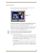
Introduction Introduction The NXD-CV5 5" Modero Widescreen Color Video Touch Panels (FIG. 1) are the industry’s first widescreen mini-touch panels and are available only through AMX. NXD-CV5 (front view) (FG2261) FIG. 1 Sample 5" Video Touch Panel This is the first 5" diagonal Widescreen Color Active video-capable touch panel in the control and automation industry. This Color Video (CV) panel displays NTSC/MPAL/PAL/SECAM video formats within variable sized windows up to 800 x 480.
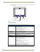
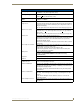
Introduction CV5 panels feature programmable firmware that can be upgraded via either the Ethernet port or the mini-USB port. NXD-CV5 (shown with Button Trim Ring installed) Programmable Buttons/LEDs (1-3) Programmable Buttons/LED (4-6) Sleep/Setup Access Button FIG. 2 NXD-CV5 (front view showing default Trim Ring) CV5 Specifications The following table outlines the specifications for the 5" Widescreen Modero panel.
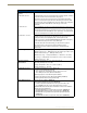
Introduction Specifications for 5" Widescreen Video Touch Panel (Cont.) Viewing Angles: • 90° total viewing angle: - Horizontal: + 45° (left and right from center) IR Reception Angle: • Horizontal: + 25° (left and right from center) • Vertical: + 15° (up and down from center) Supported Audio Sample Rates: • 48000Hz, 44100Hz, 32000Hz, 24000Hz, 22050Hz, 16000Hz, 12000Hz, 11025Hz, and 8000Hz.
Introduction Specifications for 5" Widescreen Video Touch Panel (Cont.) Side Panel Components (Cont.): Mini-USB connector: • 5-pin Mini-USB connector used for programming, firmware update, and touch panel file transfer between the PC and the target panel. Note: When connecting the panel to PC using a CC-USB (or compatible) cable, be sure to power the panel On before attempting to connect the USB cable from the PC to the mini-USB port on the panel.
Introduction Specifications for 5" Widescreen Video Touch Panel (Cont.) Other AMX Equipment (Cont.
Introduction 6 5" Modero Widescreen Touch Panel
CV5 Touch Panel Accessories CV5 Touch Panel Accessories The following section outlines and describes both the included accessories and other AMX equipment available for these touch panels. NXA-AVB/ETHERNET Breakout Box (FG2254-10) The NXA-AVB/ETHERNET Breakout Box (FIG. 4) is sold as a separate accessory to the CV5 panel and does not come as part of a Kit configuration for this panel.
CV5 Touch Panel Accessories NXA-AVB/ETHERNET Specifications (Cont.) Rear Components: • 6-pin 3.5 mm Phoenix connector for in-bound (left/right channel) audio • 4-pin 3.5 mm Phoenix connector for out-bound (from microphone) audio • BNC connector (female) for Composite or Chroma (for video-capable panels only) • BNC connector (female) for luminance (for video-capable panels only) • RJ-45 connector for Ethernet input from the control system • 2-pin 3.
CV5 Touch Panel Accessories The breakout box unit can be mounted on either a horizontal flat surface or into an equipment rack (by removing the front screws and attaching it to an optional AC-RK). The power supply being used on the NXA-AVB/ETHERNET is dependant on the power requirements of the target touch panel. Use a standard CAT5 Ethernet cable to provide both communication and 10/100 network connectivity between the panel, NXA-AVB/ETHERNET, NetLinx Master, and the network.
CV5 Touch Panel Accessories • PWR: 2-pin mini-Phoenix connector that connects to a 12 VDC-compliant power supply. This port can be used to provide power to a Modero panel by sending it through the NXA-AVB/ETHERNET (rear power connector through to the front power connector). Wiring the NXA-AVB/ETHERNET for Unbalanced Audio Most domestic audio equipment has unbalanced audio inputs and outputs.
CV5 Touch Panel Accessories The 3 wires used in a typical XLR lead are often referred to as Ground, Live (Hot) and Return (Cold). "Live" and "Return" carry the "in-phase" and "out-of-phase" versions of the audio respectively. The pins of the XLR plug/socket are as follows: • X = Ground • L = Live (Hot) • R = Return (Cold) When connecting the MIC OUT connector to a balanced audio input (FIG.
CV5 Touch Panel Accessories 12 5" Modero Widescreen Touch Panel
Installation Installation This NXD panels can be installed into either a pre-wall surface (using a CB-TP5 rough-in/wallbox) or a solid surface (using either solid surface or drywall screws). Unpacking the Panel 1. Inspect and confirm the contents of the shipment box to verify you have all specified parts. Refer to the Specifications for 5" Widescreen Video Touch Panel section on page 2 for more information about included accessories and other AMX equipment. 2.
Installation CV5 Panel/enclosure Trim Ring Latches Default Button Trim Ring (with button openings) B latch Button Button removal (showing the internal surface of Faceplate) Faceplate (outside surface shown) FIG. 10 Removing the default Button Trim Ring No-Button Trim Ring Hollow button openings Faceplate (outer surface shown) FIG. 11 Inserting the No-Button Trim Ring 8.
Installation Installing the Button Trim Ring The outer No-Button Trim Ring is secured to the Faceplate with plastic latches. In order to re-install the Button Trim Ring back onto an NXD panel which has had the default Button Trim Ring features removed; you must first remove the No-Button Trim Ring: 1. To remove the Faceplate, simply pull it away from the panel by gently tugging it outwards until the entire Faceplate comes away from the panel. 2.
Installation Button Trim Ring Faceplate (outer surface shown) Button openings FIG. 13 Inserting the Button Trim Ring Installing the Optional NXA-BEZ Colored Trim Ring Kits The Bezel Trim Ring Kits allow a user to change to both the color of the faceplate and determine whether the panel will or will not use colored pushbuttons. Each grouping has been configured so that the accompanying Faceplate, Trim Ring, and pushbuttons are color matched.
Installation NXA-BEZ Trim Ring Kits (CV5) (Cont.
Installation 3. Assemble the Kit components: To assemble the Bezel Kit with Buttons (FIG. 15): CV5 Panel/enclosure Button latch Trim Ring Latches Button installation (showing the internal surface of Faceplate) Colored Button Trim Ring Colored Faceplate (outside surface shown) FIG.
Installation No-Button Trim Ring Hollow button openings Faceplate (outer surface shown) FIG. 16 Installing the No-Button Bezel Kit (NXA-BEZ-5NB) Pre-Wall Installation of the Rough-In Box Wall Mount panels (NXDs) are contained within an outer housing (back box). This back box is not removed when installing the NXD into a CB-TP5 Rough-In Box. The back box is only removed to gain access for the replacement of the internal components.
Installation Stud Mounting tabs Wiring knockouts (6) (must be located on left side) Stud NXD Mounting tabs (should lie flush against the outside of the wall) Drywall or sheetrock FIG. 17 CB-TP5 rough-in box components Remember that when mounting this rough-in box, the NXD mounting tabs must lie flush against the outside of the sheetrock. 4.
Installation C - Optional CB-TP5 rough-in/wallbox Stud #4-40 Mounting Screws (three - included) secure the NXD to the Rough-In Box Mounting Tab B - Main NXD unit consists of the touch panel and back box housing A - Faceplate/Trim Ring default Faceplate comes with buttons FIG. 18 NXD-CV5 panel installation into a CB-TP5 (pre-wall construction) 3. Connect all data and power wiring connectors to their corresponding locations along the side of the (un-powered) NXD touch panel.
Installation 10. Reconnect the terminal power connector on the 12 VDC-compliant power supply and apply power. Installing the NXD into drywall using Expansion Clips Expansion clips are mounted through the three oval holes located along the rim of the NXD-CV5. As the screw is tightened, the clip bends toward the insertion hole and into the wall. This bending creates a "grip" on the wall by either pressing onto the wall or by securing the drywall between the housing and the drywall clip.
Installation FIG. 19 NXD-CV5 Wall Mount panel dimensions using expansion clips 6. Test the incoming wiring by attaching the panel connections to their terminal locations and applying power. Verify the panel is receiving power and functioning properly to prevent repetition of the installation. 7. Disconnect the terminal end of the power cable from the connected power supply.
Installation 3 notches are required to accommodate the three expansion clips (included) Install the 3 included drywall clip sets into these locations Drywall Clip (3) Mounting Tab A - Faceplate /Trim Ring B - Main NXD unit consists of the touch panel and back box FIG. 20 Wall Mount panel (NXD) installation configuration for drywall surfaces Don’t disconnect the connectors from the touch panel. The unit must be installed with the attached connectors before being inserted into the drywall. 8.
Installation Installing the NXD into a Flat Surface using #4 screws Mounting screws (#4, not included) are secured through circular holes located at the left and right sides of the NXD-CV5. The most important thing to remember when mounting the NXD is that the outer frame (Mounting Tabs) must be installed flush against the mounting surface. Refer to SP-2261-02 for detailed installation dimensions (reproduced in FIG. 21).
Installation 5. Connect all data and power wiring connectors to their corresponding locations along the left side of the (un-powered) NXD touch panel. Verify that the terminal end of the power cable is not connected to a power source before plugging in the 2-pin power connector. The USB connectors can be from a either a USB extension cable, or a wireless USB RF transmitter. 6. Test the incoming wiring by connecting the panel connections to their terminal locations and applying power.
Installation 10. Place the Faceplate/Trim Ring assembly (A in FIG. 22) back onto the main NXD unit (B in FIG. 22). Make sure to align the Microphone, Light, and PIR Motion sensor locations to their respective openings on the front bezel/faceplate. 11. Reconnect the terminal RJ-45, Ethernet, USB, and any optional audio/video wiring to their respective locations on either the NXA-AVB/ETHERNET Breakout Box, Ethernet port, or NetLinx Master. 12.
Installation Wiring Guidelines for the CV5 Panels The CV5 panel uses a 12 VDC-compliant power supply to provide power to the panel via the 2-pin 3.5 mm mini-Phoenix PWR connector. Use the power requirements information (page 2) to determine the power draw. The incoming PWR and GND wires from the power supply must be connected to the corresponding locations within the PWR connector. This unit should only have one source of incoming power.
Installation Audio/Video Port: Connections and Wiring The following table shows the signal and pinout/pairing information used on the RJ-45 Audio and Video connections.
Installation FIG. 25 diagrams the RJ-45 pinouts and signals for the Ethernet RJ-45 connector and cable. FIG. 25 RJ-45 wiring diagram USB Port: Connecting and Using Input Devices The CV5 panel can have up to two USB-capable input devices connected for use on its different firmware and TPD4 panel pages. These input devices can consist of a keyboard or mouse. USB-connected input devices are not detected and recognized by the panel until power is cycled to the unit.
Panel Calibration Panel Calibration This section outlines the steps for calibrating the touch panel. It is recommended that you calibrate the panel before its initial use and after completing a firmware download. Modero panels are factory setup with specific demo touch panel pages. The first splash screen that appears indicates the panel is receiving power, beginning to load firmware, and preparing to display the default touch panel pages.
Panel Calibration The request to touch the crosshairs is the first on-screen message Calibration successful is the second on-screen message that appears after the calibration process is completed On-screen crosshairs used for calibration of the touch device FIG.
Configuring Communication Configuring Communication Communication between the Modero panel and the Master is done using either USB or ETHERNET (DHCP or Static IP). Ethernet communication can only be achieved via a direct Ethernet connection (the NXA-WC802.11B/CF wireless interface card is not available on the CV5). Before commencing, verify you are using the latest NetLinx Master and Modero panel firmware. Verify you are using the latest versions of AMX’s NetLinx Studio and TPDesign4 programs.
Configuring Communication FIG. 31 Protected Setup page Before continuing, open NetLinx Studio. This program assists in developing a System Number, Master IP/URL, and Master Port number. Refer to your NetLinx Master’s instruction manuals for more information. 8. Obtain the System Number and Master IP Address from NetLinx Studio. This information must be specific for the system used with the configured Modero panel. 9. Press the grey Front Setup Access button for 3 seconds to open the Setup page. 10.
Configuring Communication It is recommended that firmware KIT files only be transferred over a direct connection and only when the panel is connected to a power supply. I The mini-USB connector MUST be plugged into an already active panel before the PC can recognize the connection and assign an appropriate USB driver. This driver is part of both the NetLinx Studio and TPDesign4 software application installations.
Configuring Communication No connection is established until the Virtual Master becomes active within Studio Red Connection Status icon indicates no connection to a Virtual Master Green Connection Status icon indicates communication to a Virtual Master FIG. 33 USB System Connection page - using a USB Connection Type ALL fields are then greyed-out and read-only, but still display any previous network information. 6. Press the Back button on the touch panel to return to the Protected Setup page. 7.
Configuring Communication The driver does not contain a Microsoft® digital signature and Windows® then informs you of such. 9. Click Yes when told that a digital signature was not found. This action accepts the installation of the new AMX USB driver. The panel is now configured to communicate directly with the PC. This process completes the association between driver and device.
Configuring Communication 5. Click the Properties button to view further information about the installed USB driver. USB detection icon FIG. 36 USB Properties windows If there is a yellow exclamation point next to the AMX USB LAN LINK device (within the hardware devices section of the Unplug or Eject Hardware window), stop and close the USB operation. Reconnect the USB cable to the panel and repeat the setup procedures. Refer to the Troubleshooting section on page 143 for more detailed information.
Configuring Communication IP Address of computer (not needed as this is a direct USB connection) FIG. 37 Assigning Communication Settings for a Virtual Master 6. Click on the Virtual Master radio box (from the Transport Connection Option section) to indicate you are wanting to configure the PC to communicate directly with a panel. Everything else such as the Authentication is greyed-out because you are not going through the Master’s UI. 7.
Configuring Communication Step 5: Confirm and View the current AMX USB device connections Use the CC-USB Type-A to Mini-B 5-wire programming cable (FG10-5965) to provide communication between the mini-USB Program port on the touch panel and the PC. This method of communication is used to transfer firmware KIT files and TPD4 touch panel files. A mini-USB connection is only detected after it is installed onto an active panel.
Configuring Communication Step 1: Configure the Panel’s Wired IP Settings This panel has only one method of communicating to a target Master over the Internet: Wired (direct Ethernet connection) (wireless communication is not available on the CV5). You can only configure the connection parameters through the System Connection page.
Configuring Communication 6. Repeat the same process for the Subnet Mask and Gateway fields. 7. Press the optional Host Name field to open the Keyboard and enter the Host Name information. 8. Press Done after you are finished assigning the alpha-numeric string of the host name. 9. Press the Primary DNS field to open a Keyboard, enter the Primary DNS Address (provided by your System Administrator) and press Done when compete. Repeat this process for the Secondary DNS field. 10.
Configuring Communication 4. Verify the green Ethernet LED (from the rear Ethernet port on the Master) is illuminated (indicating a proper connection). 5. Verify the yellow LED (from the rear Ethernet port on the Master) is blinking (indicating communication). 6. After the panel powers-up, press and hold the grey Front Setup Access button (for 3 seconds) to proceed to the Setup page. 7. Select Protected Setup > System Connection (located on the lower-left) to open the System Connection page (FIG. 39).
Configuring Communication Enter this IP into the Master IP/URL field on the System Settings page IP Addresses of computer (also obtained by using the Start > Run > cmd command) FIG. 40 Assigning Communication Settings and TCP/IP Settings for a Virtual Master 8. From within this dialog enter the System number (default is 1) and note the IP Address of the target PC being used as the Virtual Master.
Configuring Communication 14. Press the blue Type field (from the Master Connection section) until the choice cycles to the word Ethernet. 15. Press the Mode field until the choice cycles to the word URL. By selecting URL, the System Number field becomes read-only (grey) because the panel pulls this value directly from the communicating target Master (virtual or not). A Virtual Master system value can be set within the active AMX software applications such as: NetLinx Studio, TPD4, or IREdit. 16.
Configuring Communication Master Connection section - NetLinx Master Ethernet IP Address - Listen Mode In this mode, you must add the Modero panel IP Address into the URL List of the Master (using NetLinx Studio). This mode sets the Modero panel to "listen" for broadcasts from the Master (using the panel IP from its URL list). 1. Obtain either a Static IP for the Modero panel (from your System Administrator) or a DHCP Address from the IP Settings of the System Connection page.
Configuring Communication Master Connection section - NetLinx Master Ethernet IP Address - Auto Mode In this mode, enter the System Number of the NetLinx Master. This mode instructs the Modero to search for a Master that uses the same System Number (assigned within the Master Connection section) and resides on the same Subnet as itself. 1. Toggle the blue Type field until Ethernet is selected (from the Master Connection section of the System Connection page). 2.
Configuring Communication FIG. 43 G4 Web Control page 7. The Network Interface Select field is read-only and displays the method of communication to the web. Verify you have selected the proper interface connection as this field does not auto-detect the connection type being used (see below). Wired is used when a direct Ethernet connection is being used for communication to the web.
Configuring Communication 16. Press Done when you are finished entering the value. The remaining fields within the G4 Web Control Settings section of this page are read-only and cannot be altered. 17. Press the Up/Down arrows on either sides of the G4 Web Control Timeout field to increase or decrease the amount of time the panel can remain idle (no cursor movements) before the session is closed and the user is disconnected. 18. Press the Back button to open the Protected Setup page. 19.
Configuring Communication Compatible devices field (showing G4 WebControl links) G4 panels Compression Options FIG. 45 Manage WebControl Connections page (populated with compatible panels) 6. Click on the G4 panel name link associated with the target panel. A secondary web browser window appears on the screen (FIG. 46). FIG. 46 Web Control VNC installation and Password entry screens 7.
Configuring Communication IP Address of touch panel - obtained from IP Settings section of the System Connection page FIG. 47 Connection Details dialog 9. If a WebControl password was setup on the G4 WebControl page, a G4 Authentication Session password dialog box appears on the screen within the secondary browser window. 10. Enter the Web Control session password into the Session Password field (FIG. 46).
Configuring Communication 52 5" Modero Widescreen Touch Panel
Upgrading Modero Firmware Upgrading Modero Firmware Before beginning the Upgrade process: Setup and configure your NetLinx Master. Refer to the your particular NetLinx Master Instruction Manual for detailed setup procedures. Calibrate and prepare the communication pages on the Modero panel for use. Refer to the Panel Calibration section on page 31. Refer to the NetLinx Studio version 2.x or higher Help file for more information on uploading files via Ethernet. Configure your panel for a direct connection.
Upgrading Modero Firmware ALL fields are then greyed-out and read-only, but still display any previous network information. 5. Press the Back button on the touch panel to return to the Protected Setup page. 6. Press the on-screen Reboot button to both save any changes and restart the panel. Remember that the panel’s connection type must be set to USB prior to rebooting the panel and prior to inserting the USB connector. 7.
Upgrading Modero Firmware 7. From within this dialog enter the System number (default is 1). 8. Click OK three times to close the open dialogs, save your settings, and return to the main NetLinx Studio application. 9. Click the OnLine Tree tab in the Workspace window to view the devices on the Virtual System. The default System value is one. 10. Right-click on the Empty Device Tree/System entry and select Refresh System to re-populate the list.
Upgrading Modero Firmware The panel firmware is shown on the right of the listed panel. Download the latest firmware file from www.amx.com and then save the Kit file to your computer. 5. If the panel firmware being used is not current, download the latest Kit file by first logging in to www.amx.com and then navigate to Tech Center > Firmware Files and from within the Modero section of the web page locate your Modero panel. 6.
Upgrading Modero Firmware Upgrading the Modero Firmware via Ethernet (IP Address) Before beginning with this section, verify that your panel is powered and connected to the NetLinx Master through an Ethernet connection. Step 1: Prepare the Master for communication via an IP 1. Obtain the IP Address of the NetLinx Master from your System Administrator.
Upgrading Modero Firmware 8. Click the New button to open the New TCP/IP Settings dialog where you can enter both a previously obtained DHCP or Static IP Address and an associated description for the connection into their respective fields. 9. Place a checkmark within the Automatically Ping the Master Controller to ensure availability radio box to make sure the Master is initially responding online before establishing full communication. 10.
Upgrading Modero Firmware 6. Press the Back button to return to the Protected Setup page and press the on-screen Reboot button to restart the panel and save any changes. Step 3: Verify and Upgrade the panel firmware via an IP 1. Click the OnLine Tree tab in the Workspace window to view the devices on the System. The default System value is one. 2.
Upgrading Modero Firmware Selected Firmware file Description field for selected Kit file Firmware download status Device and System values listed in the Workspace window must match the System and Device values FIG. 53 Send to NetLinx Device dialog (showing Modero firmware update via IP) 11. Click Close (after the panel reboots) to return to the main program. 12. Right-click the associated System number and select Refresh System.
Firmware Pages and Descriptions Firmware Pages and Descriptions This section describes each firmware page and their specific functional elements. Setup Navigation Buttons These Setup Navigation Buttons (FIG. 54) appear on the left of the panel screen when the Setup page is currently active. Closes the Setup page Press to access the Protected Setup page for panel calibration and to access security release passwords and connection settings.
Firmware Pages and Descriptions Setup Page This page (FIG. 55) centers around basic Modero panel properties such as: Connection Status of the panel, Display Timeout, Inactivity Page Flip Time, Inactivity page file, and the Panel Brightness. Connection Status Red Connection Status icon indicates no connection to a Master Green Connection Status icon indicates communication to a Master FIG.
Firmware Pages and Descriptions Setup Page Elements (Cont.) Inactivity Page Flip Timeout: Sets the number of minutes of inactivity before the panel automatically flips to a pre-selected touch panel page. When the device goes into this inactivity mode, the LCD does not power-down. • Press the UP/DN buttons to increase/decrease the time the panel can remain inactive before it flips to the preset page. Range = 0 - 240 minutes.
Firmware Pages and Descriptions Project Information Page The Project Information page displays the TPDesign4 (TPD4) project file properties currently loaded on the selected Modero panel (FIG. 57). Refer to the TPDesign4 Touch Panel Program instruction manual for more specific information on uploading TPDesign4 files to a panel. FIG.
Firmware Pages and Descriptions Project Information Page Elements (Cont.) AMX IR 455k Assigned Port: Displays the AMX 455 kHz IR channel port used by the IR receiver on the panel. This information is pulled by the panel from AMX IR Receivers section of the TPD4 Project Properties > IR Emitters & Receivers tab. • For IR reception, this is the port that reports a push on for the corresponding IR code. • IR receivers and transmitters on G4 panels share the device address number of the panel.
Firmware Pages and Descriptions Panel Information Page Elements (Cont.) Setup Port: Displays the setup port information/value being used by the panel. High Port: Displays the high port (port count) value for the panel. High Address: Displays the high address (address count) value for the panel. High Channel: Displays the high channel (channel count) value for the panel. High Level: Displays the high level (level count) value being used by the panel.
Firmware Pages and Descriptions The only way to modify a panel’s time, without altering the Master, is to use NetLinx Code. The elements of the Time & Date Setup page are described in the table below: Time & Date Setup Page Elements Back: Returns you to the previously active touch panel page without saving changes (to save changes, use the Set Time button).
Firmware Pages and Descriptions Audio Settings Page The Audio Settings page (FIG. 60) (accessed by pressing the Audio button on the Setup page) allows you to adjust the master volume parameters and default panel sounds on the panel. FIG. 60 Audio Settings page The elements of the Audio Settings page are described in the table below: Audio Settings Page Elements Back: Saves the changes and returns you to the previously active touch panel page.
Firmware Pages and Descriptions Volume Page Elements (Cont.) Line In Level: Allows you to adjust the current Line-In volume level (being received from the communicating breakout box). • Use the UP/DN buttons to adjust the Line-In volume level (range = 0 - 100). • The Line-In Level bargraph indicates the current Line-In level. • The Mute button mutes the Line-In volume. Mic Out Level: Allows you to adjust the current Microphone volume level (being received from the communicating breakout box).
Firmware Pages and Descriptions The elements of the Video Setup page are described in the table below: Video Setup Page Elements Back: Saves the changes and returns you to the previously active touch panel page. Connection Status icon: This visual display of the connection status allows the user to have a current visual update of the panel’s connection status regardless of what page is currently active.
Firmware Pages and Descriptions Protected Setup Navigation Buttons The Protected Setup Navigation Buttons (FIG. 62) appear on the left of the panel screen when the Protected Setup page is currently active. Press to access the System Settings page where you can configure communication settings for the NetLinx Master and the panel. Press to access the Calibration page where you can calibrate the panel.
Firmware Pages and Descriptions Protected Setup Page The Protected Setup page (FIG. 63) centers around the properties used by the panel to properly communicate with the NetLinx Master. Enter the factory default password (1988) into the password keypad to access this page. Provides access to the panel firmware pages by enabling the grey front setup access button: - Setup page (after a 3 second press/hold) - Calibration page (after a 6 second press/hold) FIG.
Firmware Pages and Descriptions Protected Setup Page Elements (Cont.) System Recovery: Allows you to either reset the touch panel to factory default settings and/or wipe out all existing touch panel pages: • The Reset System Settings button allows a user to wipe out all current configuration parameters on the touch panel (such as IP Addresses, Device Number assignments, Passwords, and other presets). - Pressing this button launches a Confirmation dialog (FIG. 64) which asks you to confirm your selection.
Firmware Pages and Descriptions System Settings Page The System Settings page (FIG. 66) sets the Secondary DNS Address information with its corresponding IP communication parameters, NetLinx Master communication settings, and reads the device number assigned to the Modero panel.
Firmware Pages and Descriptions System Connection Page Elements (Cont.) IP Settings: (Cont.) MAC Address Master Connection: Type Displays a read-only field that is factory set by AMX for the built-in Ethernet interface. Sets the NetLinx Master communication values: Sets the NetLinx Master to communicate with the panel via either USB or Ethernet. This is based on the cable connection from the rear. ICSNet is not a supported option on this panel.
Firmware Pages and Descriptions Calibration Page This page (FIG. 67) allows you to calibrate the touch panel using the pre-selected touch driver. Press and hold the grey Front Setup Access button (below the Modero LCD) for 6 seconds to access the Calibration page. Press the crosshairs to calibrate the panel and return to the last active firmware page.
Firmware Pages and Descriptions G4 Web Control Page The G4 Web Control page (FIG. 68) centers around enabling and disabling both the display and control of your panel (via the web). An external PC running a VNC client (installed during the initial communication to the G4 panel) makes this possible. FIG. 68 G4 Web Control page Each panel supports the open standard Virtual Network Computing (VNC) interface.
Firmware Pages and Descriptions G4 Web Control Page Elements (Cont.) G4 Web Control Settings (Cont.): Web Control Port Allows you to enter the port value that the VNC Web Server runs on. • Default value is 5900. Maximum Number of Connections This read-only field displays the maximum number of users that can be simultaneously connected to the target panel via the web. • Default value is 1.
Firmware Pages and Descriptions A light level value between the Minimum and Maximum DIM Mode values delivers an average light level. The DIM mode Min Level can never exceed the DIM Mode Max Level. The elements of the Sensor Setup page are described in the table below: Sensor Setup Page Elements Back: Saves the changes and returns you to the previously active touch panel page.
Firmware Pages and Descriptions Sensor Setup Page Elements (Cont.) Motion Sensor: Provides the following fields: • The Motion Detection field displays a reactive button that changes color (illuminates) and displays the words "Motion Detected" when motion is detected by the Modero panel’s front motion sensor. • The Motion Sensor Port field indicates the port used to report the motion sensor channel back to the NetLinx Master (set in TPD4) (read-only).
Firmware Pages and Descriptions 7. Set the Minimum Dimmer Brightness (Dim Mode Min Level) to a comfortable level by sitting in front of the panel. You should be able to comfortably see someone sitting behind the panel without being “blinded” by the panel. 8. Move around the panel and block the direct or indirect light from the room fixtures with your body. Take note of the drop in the lighting level being detected by the panel in response to your movements. 9.
Firmware Pages and Descriptions Image Caching Page The Image Caching page (FIG. 72) configures the allocation of memory for image caching. The G4 graphics engine caches images to decrease load time of previously viewed images. RAM caching is always enabled, and images (both static and dynamic) are stored in the RAM cache as they are viewed. The size of RAM cache is automatically configured to take into account available memory versus memory that may be needed by the panel later.
Firmware Pages and Descriptions Image Caching Page Elements (Cont.) Flash/RAM Cache Expires Press the Up and Down arrows to change the amount of time the images stay in cache memory. The options are: • Never • 2 Hours • 8 Hours • 1 Day • 2 Days • 5 Days Enable: Press this button to toggle the image Flash cache option On and Off. Clear Cache: Press this button to clear both the Flash and RAM cache of all stored images. Image Cache Status: The status of the memory available versus in use.
Firmware Pages and Descriptions Clearing the image cache In the Protected Setup page: 1. Press the Cache button in the Protected Setup Navigation Buttons section. This opens the Image Cache page. 2. Press Clear Cache. This clears all image cache currently stored on the panel (both Flash and RAM). Checking image cache status In the Protected Setup page: Press the Cache button in the Protected Setup Navigation Buttons section. This opens the Image Cache page.
Firmware Pages and Descriptions Password Settings Page Back: Saves all changes and returns to the previous page. Connection Status icon: The icon in the upper-right corner of each Setup page shows online/offline state of the panel to the master. • Bright red - disconnected • Bright green - connected. Blinks when a blink message is received to dark green every 5 seconds for half a second then go back to bright green. • Bright yellow - panel missed a blink message from the master.
Firmware Pages and Descriptions Tools The Tools button provides a menu to select either the Panel Logs Page section on page 86, the Panel Statistics Page section on page 88, or the Connection Utility Page section on page 90. Select any of the options to access that page. FIG. 74 Tools menu Panel Logs Page The options on the Panel Logs page allow you to view and track the connection history of the panel (FIG. 75). FIG.
Firmware Pages and Descriptions Features on this page include: Panel Logs Page Back: Saves all changes and returns to the previous page. Connection Status icon: The icon in the upper-right corner of each Setup page shows online/offline state of the panel to the master. • Bright red - disconnected • Bright green - connected. Blinks when a blink message is received to dark green every 5 seconds for half a second then go back to bright green. • Bright yellow - panel missed a blink message from the master.
Firmware Pages and Descriptions Panel Statistics Page The options on the Panel Statistics page allow you to track the connection status for the panel. The Panel Statistics page tracks ICSP messages, Blink messages, and Ethernet connection statistics (FIG. 76). FIG. 76 Panel Statistics page Features on this page include: Panel Statistics Page Back: Saves all changes and returns to the previous page.
Firmware Pages and Descriptions Total • Received - The total Blink messages received by the panel. • Missed - The total Blink messages missed by the panel. Last 15 Minutes • Received - The total Blink messages received by the panel in the last 15 minutes. • Missed - The total Blink messages missed by the panel in the last 15 minutes. Ethernet Statistics The Ethernet connection statistics for the panel. Clear Clears all panel connection statistics. Refresh Refreshes all panel connection statistics.
Firmware Pages and Descriptions Connection Utility Page The options on the Connection Utility page allow you to utilize your panel as a site survey tool. While in this page, move around your wireless network coverage area and see if there are any weak points within the spaces between your WAPs (FIG. 77). FIG. 77 Connection Utility page Features on this page include: Connection Utility Page Close: Closes the Connection Utility popup.
Firmware Pages and Descriptions Using the Connection Utility 1. Press the Tools button in the Protected Setup Navigation Buttons section. This opens the Tools menu. 2. Within the Tools menu, press the Connection Utility button. This launches the Connection Utility popup. 3. Move the panel within your network. The Connection Information notes the IP of the connected master and the IP of your panel. The Connection Statistics show the current quality of the panel connection. 4.
Firmware Pages and Descriptions 92 5" Modero Widescreen Touch Panel
Programming Programming You can program the touch panel, using the commands in this section, to perform a wide variety of operations using Send_Commands and variable text commands. A device must first be defined in the NetLinx programming language with values for the Device: Port: System (in all programming examples - Panel is used in place of these values and represents all Modero panels). Verify you are using the latest NetLinx Master and Modero firmware.
Programming Page Commands (Cont.) @DPG Syntax: Delete a specific popup page from specified popup group if it exists. Variable: "'@DPG-;'" popup page name = 1 - 50 ASCII characters. Name of the popup page. popup group name = 1 - 50 ASCII characters. Name of the popup group. Example: SEND_COMMAND Panel,"'@DPG-Popup1;Group1'" Deletes the popup page ’Popup1’ from the popup group ’Group1’.
Programming Page Commands (Cont.) @PPA Close all popups on a specified page. If the page name is empty, the current page is used. Same as the ’Clear Page’ command in TPDesign4. Syntax: "'@PPA-'" Variable: page name = 1 - 50 ASCII characters. Name of the page the popup is displayed On. Example: SEND_COMMAND Panel,"'@PPA-Page1'" Close all popups on Page1. @PPF Deactivate a specific popup page on either a specified page or the current page.
Programming Page Commands (Cont.) @PPM Set the modality of a specific popup page to Modal or NonModal. A Modal popup page, when active, only allows you to use the buttons and features on that popup page. All other buttons on the panel page are inactivated. Syntax: "'@PPM-;'" Variable: popup page name = 1 - 50 ASCII characters. Name of the popup page. mode = NONMODAL converts a previously Modal popup page to a NonModal. MODAL converts a previously NonModal popup page to Modal.
Programming Page Commands (Cont.) @PSE Set the show effect for the specified popup page to the named show effect. Syntax: "'@PSE-;'" Variable: popup page name = 1 - 50 ASCII characters. Name of the page the popup is displayed On. show effect name = Refers to the popup effect name being used. Example: SEND_COMMAND Panel,"'@PSE-Popup1;Slide from Left'" Sets the Popup1 show effect name to ’Slide from Left’. @PSP Set the show effect position.
Programming Page Commands (Cont.) PPOF Deactivate a specific popup page on either a specified page or the current page. If the page name is empty, the current page is used (see example 2). If the popup page is part of a group, the whole group is deactivated. This command works in the same way as the ’Hide Popup’ command in TPDesign4. Syntax: "'PPOF-;'" Variable: popup page name = 1 - 50 ASCII characters. Name of the popup page. page name = 1 - 50 ASCII characters.
Programming Programming Numbers The following information provides the programming numbers for colors, fonts, and borders. Colors can be used to set the colors on buttons, sliders, and pages. The lowest color number represents the lightest color-specific display; the highest number represents the darkest display. For example, 0 represents light red, and 5 is dark red. RGB triplets and names for basic 88 colors RGB Values for all 88 Basic Colors Index No.
Programming RGB Values for all 88 Basic Colors (Cont.) 100 Index No.
Programming RGB Values for all 88 Basic Colors (Cont.) Index No. Name Red Green Blue 80 Grey8 119 119 119 81 Grey10 85 85 85 82 Grey12 51 51 51 83 Grey13 34 34 34 84 Grey2 221 221 221 85 Grey11 68 68 68 86 Grey14 17 17 17 87 Black 0 0 0 255 TRANSPARENT 99 53 99 Font styles and ID numbers Font styles can be used to program the text fonts on buttons, sliders, and pages.
Programming Border styles and Programming numbers Border styles can be used to program borders on buttons, sliders, and popup pages. Border Styles and Programming Numbers No. Border styles No.
Programming TPD4 Border Styles by Name (Cont.) No. Border styles No.
Programming TPD4 Border Styles by Name (Cont.) No. Border styles No.
Programming "^" Button Commands ^ANI Run a button animation (in 1/10 second). Syntax: "'^ANI-,,,
Programming "^" Button Commands (Cont.) ^BCB Only if the specified border color is not the same as the current color. Set the border color to the specified color. Note: Color can be assigned by color name (without spaces), number or R,G,B value (RRGGBB or RRGGBBAA). Syntax: "'^BCB-,
Programming "^" Button Commands (Cont.) ^BCT Only if the specified text color is not the same as the current color. Set the text color to the specified color. Note: Color can be assigned by color name (without spaces), number or R,G,B value (RRGGBB or RRGGBBAA). Syntax: "'^BCT-,
Programming "^" Button Commands (Cont.) ^BIM Syntax: Set the input "'^BIM-,'" mask for the Variable: specified address. variable text address range = 1 - 4000. input mask = Refer to theText Area Input Masking section on page 148 for character types. Example: SEND_COMMAND Panel,"'^BIM-500,AAAAAAAAAA'" Sets the input mask to ten ’A’ characters, that are required, to either a letter or digit (entry is required).
Programming "^" Button Commands (Cont.) ^BMC Button copy command. Copy attributes of the source button to all the destination buttons. Note that the source is a single button state. Each state must be copied as a separate command. The section represents what attributes will be copied. All codes are 2 char pairs that can be separated by comma, space, percent or just ran together.
Programming "^" Button Commands (Cont.) ^BMF Set any/all button parameters by sending embedded codes and data. Syntax: "'^BMF-,
Programming "^" Button Commands (Cont.) ^BMF (Cont.) For some of these commands and values, refer to theRGB Values for all 88 Basic Colors table on page 99. ’%CF’ = Set Fill Color. ’%CB’ = Set Border Color. ’%CT’ = Set Text Color. ’%SW<1 or 0>’ = Show/hide a button. ’%SO’ = Set the button sound. ’%EN<1 or 0>’ = Enable/disable a button. ’%WW<1 or 0>’ = Word wrap On/Off. ’%GH’ = Set the bargraph upper limit.
Programming "^" Button Commands (Cont.) ^BMI Set the button mask image. Mask image is used to crop a borderless button to a non-square shape. This is typically used with a bitmap. Syntax: "'^BMI-,
Programming "^" Button Commands (Cont.) ^BNN Syntax: Set the TakeNote network name for the specified Addresses. Variable: "'^BNN-,'" variable text address range = 1 - 4000. network name = Use a valid IP Address. Example: SEND_COMMAND Panel,"'^BNN-973,192.168.169.99'" Sets the TakeNote button network name to 192.168.169.99. ^BNT Set the TakeNote network port for the specified Addresses.
Programming "^" Button Commands (Cont.) ^BOR Set a border to a specific border style associated with a border value for those buttons with a defined address range. Refer to theBorder Styles and Programming Numbers table on page 102 for more information. Syntax: "'^BOR-,'" Variable: variable text address range = 1 - 4000. border style name = Refer to the Border Styles and Programming Numbers table on page 102. border value = 0 - 41.
Programming "^" Button Commands (Cont.) ^BRD Set the border of a button state/ states. Only if the specified border is not the same as the current border. The border names are available through the TPDesign4 border-name drop-down list. Syntax: "'^BRD-,
Programming "^" Button Commands (Cont.) ^BVL Syntax: Log-On/Log-Off the computer control connection. Variable: "'^BVL-,'" variable text address range = 1 - 4000. connection = 0 (Log-Off connection) and 1 (Log-On connection). Example: SEND_COMMAND Panel,"'^BVL-500,0'" Logs-off the computer control connection of the button.
Programming "^" Button Commands (Cont.) ^CPF Clear all page flips from a button. Syntax: "'^CPF-'" Variable: variable text address range = 1 - 4000. Example: SEND_COMMAND Panel,"'^CPF-500'" Clears all page flips from the button. ^DPF Delete page flips from button if it already exists. Syntax: "'^DFP-,,'" Variable: variable text address range = 1 - 4000.
Programming "^" Button Commands (Cont.) ^GDI Change the bargraph drag increment. Syntax: "'^GDI-,'" Variable: variable text address range = 1 - 4000. bargraph drag increment = The default drag increment is 256. Example: SEND_COMMAND Panel,"'^GDI-7,128'" Sets the bargraph with variable text 7 to a drag increment of 128. ^GIV Invert the joystick axis to move the origin to another corner.
Programming "^" Button Commands (Cont.) ^GRD Change the bargraph ramp-down time in 1/10th of a second. Syntax: "'^GRD-,'" Variable: variable text address range = 1 - 4000. bargraph ramp down time = In 1/10th of a second intervals. Example: SEND_COMMAND Panel,"'^GRD-500,200'" Changes the bargraph ramp down time to 20 seconds. ^GRU Change the bargraph ramp-up time in 1/10th of a second.
Programming "^" Button Commands (Cont.) ^ICO Set the icon to a button. Syntax: "'^ICO-,
Programming "^" Button Commands (Cont.) ^JST The alignment of 0 is followed by ',,'. The left and top coordinates are relative to the upper left corner of the button. Set text alignment using a Syntax: numeric keypad "'^JST-,
Programming "^" Button Commands (Cont.) ^TEC Set the text effect color for the specified addresses/states to the specified color. The Text Effect is specified by name and can be found in TPD4. You can also assign the color by name or RGB value (RRGGBB or RRGGBBAA). Syntax: "'^TEC-,
Programming "^" Button Commands (Cont.) ^UNI Set Unicode text. For the ^UNI command (%UN and ^BMF command), the Unicode text is sent as ASCII-HEX nibbles. Syntax: "'^UNI-,
Programming Text Effect Names The following is a listing of text effects names. This list is associated with the ^TEF command on page 122.
Programming Button Query Commands Button Query commands reply back with a custom event. There will be one custom event for each button/state combination. Each query is assigned a unique custom event type.
Programming All custom events have the following 6 fields: Custom Event Fields Field Description Uint Flag 0 means text is a standard string, 1 means Unicode encoded string slong value1 button state number slong value2 actual length of string (this is not encoded size) slong value3 index of first character (usually 1 or same as optional index string text the text from the button text length (string encode) button text length These fields are populated differently for each query command.
Programming Button Query Commands (Cont.) ?BCF Get the current fill color. Syntax: "'?BCF-,
Programming Button Query Commands (Cont.) ?BMP Get the current bitmap name. Syntax: "'?BMP-,
Programming Button Query Commands (Cont.) ?BRD Get the current border name. Syntax: "'?BRD-,
Programming Button Query Commands (Cont.) ?FON Get the current font index. Syntax: "'?FON-,
Programming Button Query Commands (Cont.) ?JSB Get the current bitmap justification. Syntax: "'?JSB-,
Programming Button Query Commands (Cont.) ?JST Get the current text justification. Syntax: "'?JST-,
Programming Button Query Commands (Cont.) ?TEF Get the current text effect name. Syntax: "'?TEF-,
Programming Panel Runtime Operations Serial Commands are used in the AxcessX Terminal Emulator mode. These commands are case insensitive. Panel Runtime Operation Commands ABEEP Output a single beep even if beep is Off. Syntax: "'ABEEP'" Example: SEND COMMAND Panel,"'ABEEP'" Outputs a beep of duration 1 beep even if beep is Off. ADBEEP Output a double beep even if beep is Off. Syntax: "'ADBEEP'" Example: SEND COMMAND Panel,"'ADBEEP'" Outputs a double beep even if beep is Off.
Programming Panel Runtime Operation Commands (Cont.) @AKP Pop up the keypad icon and initialize the text string to that specified. Keypad string is set to null on power up and is stored until power is lost. The Prompt Text is optional. Syntax: "'@AKP-;'" Variables: initial text = 1 - 50 ASCII characters. prompt text = 1 - 50 ASCII characters.
Programming Panel Runtime Operation Commands (Cont.) @EKP Extend the Keypad. Pops up the keypad icon and initializes the text string to that specified. The Prompt Text is optional. Syntax: "'@EKP-;'" Variables: initial text = 1 - 50 ASCII characters. prompt text = 1 - 50 ASCII characters. Example: SEND COMMAND Panel,"'@EKP-33333333;Enter Password'" Pops up the Keypad and initializes the text string '33333333' with prompt text 'Enter Password'. PKEYP Present a private keypad.
Programming Panel Runtime Operation Commands (Cont.) @SOU Play a sound file. Syntax: "'@SOU-'" Variables: sound name = Name of the sound file. Supported sound file formats are: WAV & MP3. Example: SEND COMMAND Panel,"'@SOU-Music.wav'" Plays the 'Music.wav' file. @TKP Present a telephone keypad. Pops up the keypad icon and initializes the text string to that specified. The Prompt Text is optional. Syntax: "'@TKP-;'" Variables: initial text = 1 - 50 ASCII characters.
Programming Input Commands These Send Commands are case insensitive. Input Commands ^CAL Put panel in calibration mode. Syntax: "'^CAL'" Example: SEND COMMAND Panel,"'^CAL'" Puts the panel in calibration mode. ^KPS Set the keyboard passthru. Syntax: "'^KPS-'" Variable: pass data: = Disables the keyboard. 0 = Pass data to G4 application (default). This can be used with VPC or text areas. 1 - 4 = Not used. 5 = Sends out data to the Master.
Programming Embedded codes The following is a list of G4 compatible embedded codes: Embedded Codes Decimal numbers Hexidecimal values Virtual keystroke 8 ($08) Backspace 13 ($0D) Enter 27 ($1B) ESC 128 ($80) CTRL key down 129 ($81) ALT key down 130 ($82) Shift key down 131 ($83) F1 132 ($84) F2 133 ($85) F3 134 ($86) F4 135 ($87) F5 136 ($88) F6 137 ($89) F7 138 ($8A) F8 139 ($8B) F9 140 ($8C) F10 141 ($8D) F11 142 ($8E) F12 143 ($8F) Num Lock 144
Programming Panel Setup Commands These commands are case insensitive. Panel Setup Commands ^MUT Set the panel mute state. Syntax: "'^MUT-'" Variable: mute state= 0 = Mute Off and 1 = Mute On. Example: SEND_COMMAND Panel,"'^MUT-1''" Sets the panel’s master volume to mute. @PWD @PWD sets the level 1 password only. Set the page flip password. Syntax: "'@PWD-'" Variables: page flip password = 1 - 50 ASCII characters.
Programming Dynamic Image Commands The following is a listing and descriptions of Dynamic Image Commands. Dynamic Image Commands ^BBR Set the bitmap of a button to use a particular resource. Syntax: "'^BBR-,
Programming Dynamic Image Commands (Cont.) ^RAF Adds any and all resource parameters by sending embedded codes and data. Add new resources. Syntax: "'^RAF-,'" Variable: resource name = 1 - 50 ASCII characters. data = Refers to the embedded codes, see table below. Embedded Codes: Parameter Embedded Code Description protocol ’%P<0-1>’ Set protocol. HTTP (0) or FTP (1). user ’%U’ Set Username for authentication. password ’%S’ Set Password for authentication.
Troubleshooting Troubleshooting This section describes the solutions to possible hardware/firmware issues that could arise during the common operation of a Modero touch panel. Troubleshooting Information Symptom Solution My USB drivers has a yellow exclamation point and doesn’t appear to be working. The USB driver was incorrectly installed and should be re-installed: • Power up the panel without the USB cable connected to the panel. • Plug in the USB cable into the G4 panel.
Troubleshooting Troubleshooting Information (Cont.) Symptom Solution My Modero panel isn’t appearing in my Workspace window. • Verify that the System number is the same on both the NetLinx Workspace window and the System Connection page on the Modero panel. • Verify you have entered the proper NetLinx Master IP and connection methods into the Master Connection section of the System Connection page.
Troubleshooting Troubleshooting Information (Cont.) Symptom Solution My on-screen mouse cursor doesn’t appear. • The USB connections are not detected until after the particular USB connection plugged into the corresponding port on the panel and power is cycled to the panel. Calibration is not working. • After the Modero touch panel has been updated with a new firmware kit (downloaded to the panel through NetLinx Studio), the calibration could need to be reset.
Troubleshooting Troubleshooting Information (Cont.) Symptom Solution I have more that one Modero panel connected to my System Master and only one shows up. Multiple NetLinx Compatible devices (such as Modero panels) can be associated for use with a single Master. Each Modero panel comes with a defaulted Device Number value of 10001. When using multiple panels, it can become very easy to overlook the need to assign different Device Number values to each panel.
Appendix A Appendix A Text Formatting Codes for Bargraphs/Joysticks Text formatting codes for bargraphs provide a mechanism to allow a portion of a bargraphs text to be dynamically provided information about the current status of the level (multistate and traditional). These codes would be entered into the text field along with any other text.
Appendix A Text Area Input Masking Text Area Input Masking can be used to limit the allowed/correct characters that are entered into a text area. For example, in working with a zip code, a user could limit the entry to a max length of only 5 characters but, with input masking, you could limit them to 5 mandatory numerical digits and 4 optional numerical digits. A possible use for this feature is to enter information into form fields.
Appendix A Refer to the following Send Commands for more detailed information: • ^BIM - Sets the input mask for the specified addresses. (see the ^BIM section on page 108). • ^BMF subcommand %MK - sets the input mask of a text area (see the ^BMF section on page 110). Input mask ranges These ranges allow a user to specify the minimum and maximum numeric value for a field. Only one range is allowed per field. Using a range implies a numeric entry ONLY.
Appendix A A keyboard entry using normal text entry is straightforward. However, once an input mask is applied, the behavior of the keyboard needs to change to accommodate the input mask's requirement. When working with masks, any literal characters in the mask will be "skipped" by any cursor movement including cursor keys, backspace, and delete. When operating with a mask, the mask should be displayed with placeholders. The "-" character should display where you should enter a character.
Appendix A URL Resources A URL can be broken into several parts. For example: the URL http://www.amx.com/company-infohome.asp. This URL indicates that the protocol in use is http (HyperText Transport Protocol) and that the information resides on a host machine named www.amx.com. The image on that host machine is given an assignment (by the program) name of company-info-home.asp (Active Server Page). The exact meaning of this name on the host machine is both protocol dependent and host dependent.
Appendix A 152 5" Modero Widescreen Touch Panel
Appendix A 5" Modero Widescreen Touch Panel 153
Appendix A 154 5" Modero Widescreen Touch Panel
Appendix A 5" Modero Widescreen Touch Panels 155
AMX. All rights reserved. AMX and the AMX logo are registered trademarks of AMX. AMX reserves the right to alter specifications without notice at any time. ©2008 10/2008 It’s Your World - Take Control™ 3000 RESEARCH DRIVE, RICHARDSON, TX 75082 USA • 800.222.0193 • 469.624.8000 • 469-624-7153 fax • 800.932.6993 technical support • www.amx.