
Specifications
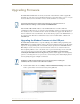
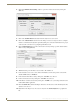
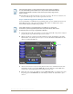
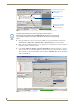
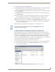
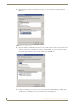
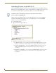

Table Of Contents
- MVP-5100/5150 Modero® ViewPoint® Touch Panels, 5.2" and 5”
- Introduction
- Accessories
- Configuring Communication
- Overview
- IR Communication
- Modero Setup and System Settings
- Wireless Settings - Wireless Access Overview (MVP-5150 Only)
- Configuring Wireless Network Access (MVP-5150 Only)
- Step 1: Configure the Device’s Wireless IP Settings (MVP- 5150 Only)
- Step 2: Configure the Card’s Wireless Security Settings
- Panel Downloads and Firmware Updates
- Setup Pages
- Protected Setup Pages
- Upgrading Firmware
- Programming
- Overview
- Page Commands
- Programming Numbers
- "^" Button Commands
- ^ANI
- ^APF
- ^BAT
- ^BAU
- ^BCB
- ^BCF
- ^BCT
- ^BDO
- ^BFB
- ^BIM
- ^BLN
- ^BMC
- ^BMF
- ^BMI
- ^BML
- ^BMP
- ^BNC
- ^BNN
- ^BNT
- ^BOP
- ^BOR
- ^BOS
- ^BPP
- ^BRD
- ^BSF
- ^BSM
- ^BSO
- ^BSP
- ^BVL
- ^BVN
- ^BVP
- ^BVT
- ^BWW
- ^CPF
- ^DLD
- ^DPF
- ^ENA
- ^FON
- ^GDI
- ^GIV
- ^GLH
- ^GLL
- ^GRD
- ^GRU
- ^GSC
- ^GSN
- ^ICO
- ^IRM
- ^JSB
- ^JSI
- ^JST
- ^MBT
- ^MDC
- ^SHO
- ^TEC
- ^TEF
- ^TOP
- ^TXT
- ^UNI
- Miscellaneous MVP Strings back to the Master
- MVP Panel Lock Passcode commands
- Text Effects Names
- Button Query Commands
- Panel Runtime Operations
- Input Commands
- Embedded codes
- Panel Setup Commands
- Battery Life and Replacement
- Appendix A: Text Formatting
- Appendix B: Wireless Technology
- Appendix C: Troubleshooting
- Overview
- Panel Doesn’t Respond To Touches
- Battery Will Not Hold Or Take A Charge
- MVP Isn’t Appearing In The Online Tree Tab
- MVP Can’t Obtain a DHCP Address
- My WEP Doesn’t Seem To Be Working
- NetLinx Studio Only Detects One Of My Connected Masters
- Can’t Connect To a NetLinx Master
- Only One Modero Panel In My System Shows Up
- Panel Behaves Strangely After Downloading A Panel File Or Firmware
- Overview
Upgrading Firmware
93
MVP-5100/5150 5.2" Modero Viewpoint Touch Panels
8. Select the panel’s Kit file from the Files section.
9. Enter the Device value associated with the panel and the System number associated with the Master
(listed in the OnLine Tree tab of the Workspace window). The Port field is greyed-out.
10. Click the Reboot Device checkbox. This causes the touch panel to reboot after the firmware update
process is complete.
11. Click Send to begin the transfer. The file transfer progress is indicated on the bottom-right of the
dialog (B in FIG. 69).
12. After the file transfer is complete, the panel will automatically reboot. As the panel is rebooting,
temporarily unplug the USB connector on the panel until the panel has completely restarted.
13. Once the first panel page has been displayed, reconnect the USB connector to the panel.
14. Right-click the associated System number and select Refresh System. This causes a refresh of all
project systems, establishes a new connection to the Master, and populates the System list with
devices on your particular system.
15. Confirm that the panel has been properly updated to the correct firmware version.
A Special Note for Network Interface Connections
Due to any USB connection to your PC being made through a Network Interface Connection (NIC),
Windows will automatically make any new NIC connection the Primary connection. If this happens, the
USB address of 12.0.0.x will show up across the PC’s network switches as the PC’s source address. In
some cases, network administrators will notice the NIC connection and reconfigure any PC that has
connected to the MVP-5100. Business, college, and government installations are the type of installations
that would be most affected, and most home installations would not be affected.
To prevent the NIC connection from becoming the primary connection:
1. From the Windows Start menu, select Settings > Control Panel to open the Control Panel window.
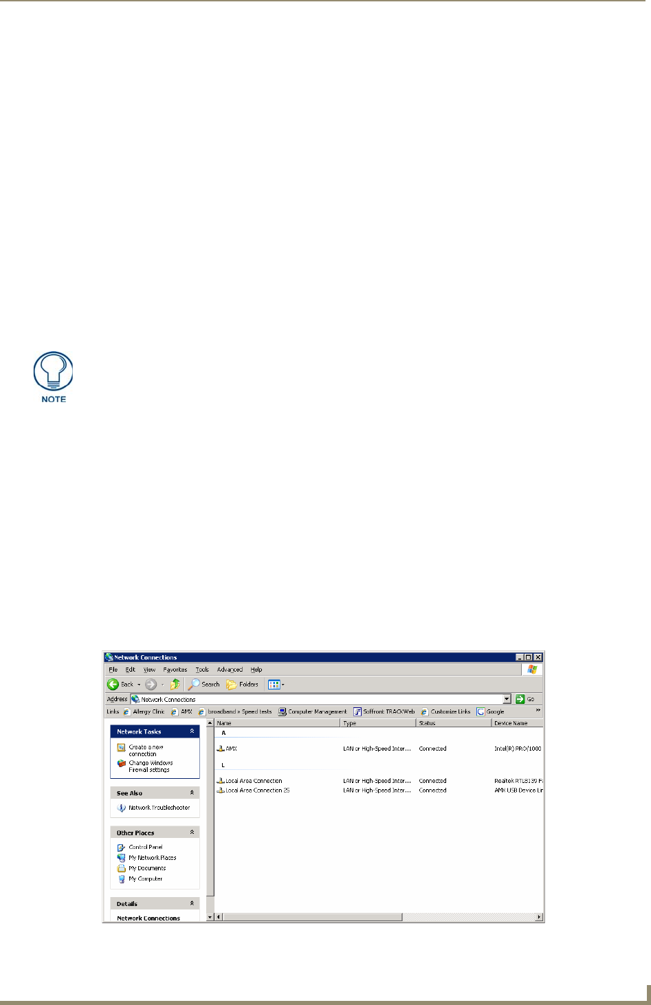
2. In the Control Panel window, click on the Network Connections icon to open the Network
Connections window (FIG. 70)
Verify you have downloaded the latest firmware file from www.amx.com and then
save the Kit file to your computer.
FIG. 70 Network Connections window