
Specifications
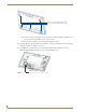
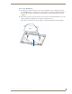

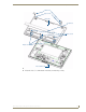

Table Of Contents
- MVP-5100/5150 Modero® ViewPoint® Touch Panels, 5.2" and 5”
- Introduction
- Accessories
- Configuring Communication
- Overview
- IR Communication
- Modero Setup and System Settings
- Wireless Settings - Wireless Access Overview (MVP-5150 Only)
- Configuring Wireless Network Access (MVP-5150 Only)
- Step 1: Configure the Device’s Wireless IP Settings (MVP- 5150 Only)
- Step 2: Configure the Card’s Wireless Security Settings
- Panel Downloads and Firmware Updates
- Setup Pages
- Protected Setup Pages
- Upgrading Firmware
- Programming
- Overview
- Page Commands
- Programming Numbers
- "^" Button Commands
- ^ANI
- ^APF
- ^BAT
- ^BAU
- ^BCB
- ^BCF
- ^BCT
- ^BDO
- ^BFB
- ^BIM
- ^BLN
- ^BMC
- ^BMF
- ^BMI
- ^BML
- ^BMP
- ^BNC
- ^BNN
- ^BNT
- ^BOP
- ^BOR
- ^BOS
- ^BPP
- ^BRD
- ^BSF
- ^BSM
- ^BSO
- ^BSP
- ^BVL
- ^BVN
- ^BVP
- ^BVT
- ^BWW
- ^CPF
- ^DLD
- ^DPF
- ^ENA
- ^FON
- ^GDI
- ^GIV
- ^GLH
- ^GLL
- ^GRD
- ^GRU
- ^GSC
- ^GSN
- ^ICO
- ^IRM
- ^JSB
- ^JSI
- ^JST
- ^MBT
- ^MDC
- ^SHO
- ^TEC
- ^TEF
- ^TOP
- ^TXT
- ^UNI
- Miscellaneous MVP Strings back to the Master
- MVP Panel Lock Passcode commands
- Text Effects Names
- Button Query Commands
- Panel Runtime Operations
- Input Commands
- Embedded codes
- Panel Setup Commands
- Battery Life and Replacement
- Appendix A: Text Formatting
- Appendix B: Wireless Technology
- Appendix C: Troubleshooting
- Overview
- Panel Doesn’t Respond To Touches
- Battery Will Not Hold Or Take A Charge
- MVP Isn’t Appearing In The Online Tree Tab
- MVP Can’t Obtain a DHCP Address
- My WEP Doesn’t Seem To Be Working
- NetLinx Studio Only Detects One Of My Connected Masters
- Can’t Connect To a NetLinx Master
- Only One Modero Panel In My System Shows Up
- Panel Behaves Strangely After Downloading A Panel File Or Firmware
- Overview
Battery Life and Replacement
154
MVP-5100/5150 5.2" Modero Viewpoint Touch Panels
Reconnecting the Battery To The Device
1.
On the back cover, make sure that the battery connector wiring runs to the right. Make sure that the
excess battery wiring fits in the space to the bottom left of the battery placement (FIG. 87). The
battery wiring may be looped around the support if necessary; make sure that the battery is not
crimped or damaged upon closure of the case.
2. Make sure to seat fully the battery plug to the connector in the device (FIG. 85). If fingers cannot be
used, use a clean, nonconductive stick or probe to seat the plug in the connector.
3. Reattach the back of the device, engaging the hook on the lower left of the case (near the speaker)
and using it to swing the back down into place.
4. Insert the five screws and replace the rubber feet atop the two upper screws, using the replacement
rubber feet included in the Battery Pack Kit (FIG. 88). Replace the bottom rubber foot over the three
lower screws, using the replacement large rubber foot included in the Battery Pack Kit.
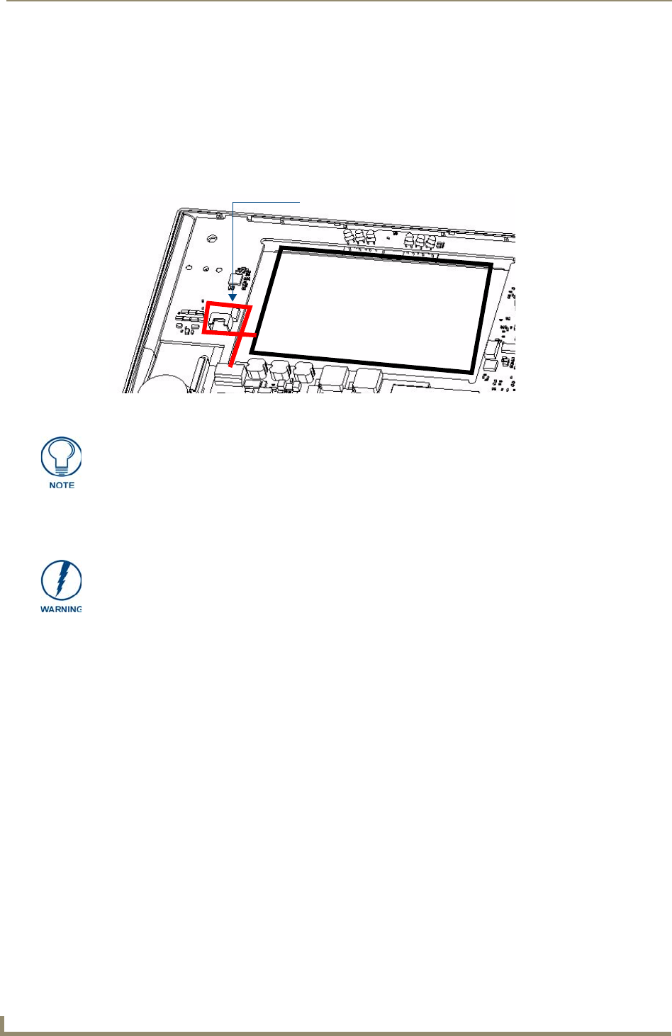
FIG. 87 Path of excess battery wiring
MVP-BP-51H battery placement
Excess battery wiring path
Special care must be taken to seat the battery plug so that it does not damage or rub
against the two resistors near the battery connector. When connecting the battery, do
not allow the battery plug to rub against the circuit board.
When reassembling the device, take especial care not to pinch or squeeze the
connector wiring or the battery. Do not force the back cover onto the device, as this
can damage the device.