
Specifications

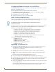
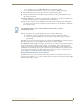


Table Of Contents
- MVP-5100/5150 Modero® ViewPoint® Touch Panels, 5.2" and 5”
- Introduction
- Accessories
- Configuring Communication
- Overview
- IR Communication
- Modero Setup and System Settings
- Wireless Settings - Wireless Access Overview (MVP-5150 Only)
- Configuring Wireless Network Access (MVP-5150 Only)
- Step 1: Configure the Device’s Wireless IP Settings (MVP- 5150 Only)
- Step 2: Configure the Card’s Wireless Security Settings
- Panel Downloads and Firmware Updates
- Setup Pages
- Protected Setup Pages
- Upgrading Firmware
- Programming
- Overview
- Page Commands
- Programming Numbers
- "^" Button Commands
- ^ANI
- ^APF
- ^BAT
- ^BAU
- ^BCB
- ^BCF
- ^BCT
- ^BDO
- ^BFB
- ^BIM
- ^BLN
- ^BMC
- ^BMF
- ^BMI
- ^BML
- ^BMP
- ^BNC
- ^BNN
- ^BNT
- ^BOP
- ^BOR
- ^BOS
- ^BPP
- ^BRD
- ^BSF
- ^BSM
- ^BSO
- ^BSP
- ^BVL
- ^BVN
- ^BVP
- ^BVT
- ^BWW
- ^CPF
- ^DLD
- ^DPF
- ^ENA
- ^FON
- ^GDI
- ^GIV
- ^GLH
- ^GLL
- ^GRD
- ^GRU
- ^GSC
- ^GSN
- ^ICO
- ^IRM
- ^JSB
- ^JSI
- ^JST
- ^MBT
- ^MDC
- ^SHO
- ^TEC
- ^TEF
- ^TOP
- ^TXT
- ^UNI
- Miscellaneous MVP Strings back to the Master
- MVP Panel Lock Passcode commands
- Text Effects Names
- Button Query Commands
- Panel Runtime Operations
- Input Commands
- Embedded codes
- Panel Setup Commands
- Battery Life and Replacement
- Appendix A: Text Formatting
- Appendix B: Wireless Technology
- Appendix C: Troubleshooting
- Overview
- Panel Doesn’t Respond To Touches
- Battery Will Not Hold Or Take A Charge
- MVP Isn’t Appearing In The Online Tree Tab
- MVP Can’t Obtain a DHCP Address
- My WEP Doesn’t Seem To Be Working
- NetLinx Studio Only Detects One Of My Connected Masters
- Can’t Connect To a NetLinx Master
- Only One Modero Panel In My System Shows Up
- Panel Behaves Strangely After Downloading A Panel File Or Firmware
- Overview

Appendix B: Wireless Technology
170
MVP-5100/5150 5.2" Modero Viewpoint Touch Panels
Configuring Modero Firmware via the USB Port
The MVP-5100 and MVP-5150 need to be configured to connect with a PC to transfer firmware via the mini-
USB port. To configure the touch panel:
Prepare NetLinx Studio For Communication Via the USB Port
1.
From the Start menu in Windows XP, open the Network Connections dialog (Start > Settings >
Network Connections > Local Area Connection).
2. In the TCP/IP Properties dialog box, click OK.
3. In the Local Area Connection Properties, section, click Close.
AMX Certificate Upload Utility
The Certificate Upload utility gives you the ability to compile a list of target touch panels, select a pre-obtained
certificate (uniquely identifying the panel), and then upload that file to the selected panel.
This application ensures that a unique certificate is securely uploaded to a specific touch panel. Currently, the
target panels must be capable of supporting the WPA-PSK and EAP-XXX wireless security formats.
The Certificate Upload utility supports the following capabilities:
Ability to browse both a local and network drive to find a desired certificate file.
Ability to create a list of target AMX G4 touch panels based on IP Addresses.
Ability to display the IP Address of the local computer hosting the application.
Ability to load a previously created list of target touch panels.
Ability to save the current list of target Modero panel as a file.
Ability to track the progress of the certificate upload by noting the current data size being
transmitted and any associated error messages (if any).
The Certificate Upload Utility recognizes the following certificate file types:
CER (Certificate File)
DER (Distinguished Encoding Rules)
PEM (Privacy Enhanced Mail)
PFX (Normal Windows generated certificate)
PVK (Private Key file)
Uploading a Certificate File
1. Install the latest AMX USB LAN LINK driver onto your computer by installing the latest versions of
either TPDesign4 or NetLinx Studio2. This USB driver prepares your computer for proper
communication with the MVP-5200i.
2. Access the target panel's Protected Setup firmware page and configure the USB communication
parameters.
3. With the panel successfully communicating with the target computer, launch the Certificate Upload
Utility.
Familiarize yourself with the Certificate Utility User Interface options.
4. Locate your certificate file by using the Browse button and navigating to the desired file type.
5. Use the drop-down arrow in the Local Address field to select direct communication through the USB port.
6. Select the 10.XX.XX.1 IP Address that corresponds to the virtual IP Address assigned to the USB
connection port on the computer.
7. Navigate to the Add IP Address field at the bottom-right of the interface and enter a value of 1 greater than
the virtual USB IP Address.
For example: If the virtual USB IP Address is 10.0.0.1, then add an address for the directly connected
panel of 10.0.0.2. This is one greater than the USB address value detected by the utility.
This application must be run from a local machine and should not be used from a
remote network location.