
Specifications

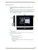
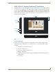
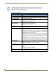
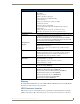

Table Of Contents
- MVP-5100/5150 Modero® ViewPoint® Touch Panels, 5.2" and 5”
- Introduction
- Accessories
- Configuring Communication
- Overview
- IR Communication
- Modero Setup and System Settings
- Wireless Settings - Wireless Access Overview (MVP-5150 Only)
- Configuring Wireless Network Access (MVP-5150 Only)
- Step 1: Configure the Device’s Wireless IP Settings (MVP- 5150 Only)
- Step 2: Configure the Card’s Wireless Security Settings
- Panel Downloads and Firmware Updates
- Setup Pages
- Protected Setup Pages
- Upgrading Firmware
- Programming
- Overview
- Page Commands
- Programming Numbers
- "^" Button Commands
- ^ANI
- ^APF
- ^BAT
- ^BAU
- ^BCB
- ^BCF
- ^BCT
- ^BDO
- ^BFB
- ^BIM
- ^BLN
- ^BMC
- ^BMF
- ^BMI
- ^BML
- ^BMP
- ^BNC
- ^BNN
- ^BNT
- ^BOP
- ^BOR
- ^BOS
- ^BPP
- ^BRD
- ^BSF
- ^BSM
- ^BSO
- ^BSP
- ^BVL
- ^BVN
- ^BVP
- ^BVT
- ^BWW
- ^CPF
- ^DLD
- ^DPF
- ^ENA
- ^FON
- ^GDI
- ^GIV
- ^GLH
- ^GLL
- ^GRD
- ^GRU
- ^GSC
- ^GSN
- ^ICO
- ^IRM
- ^JSB
- ^JSI
- ^JST
- ^MBT
- ^MDC
- ^SHO
- ^TEC
- ^TEF
- ^TOP
- ^TXT
- ^UNI
- Miscellaneous MVP Strings back to the Master
- MVP Panel Lock Passcode commands
- Text Effects Names
- Button Query Commands
- Panel Runtime Operations
- Input Commands
- Embedded codes
- Panel Setup Commands
- Battery Life and Replacement
- Appendix A: Text Formatting
- Appendix B: Wireless Technology
- Appendix C: Troubleshooting
- Overview
- Panel Doesn’t Respond To Touches
- Battery Will Not Hold Or Take A Charge
- MVP Isn’t Appearing In The Online Tree Tab
- MVP Can’t Obtain a DHCP Address
- My WEP Doesn’t Seem To Be Working
- NetLinx Studio Only Detects One Of My Connected Masters
- Can’t Connect To a NetLinx Master
- Only One Modero Panel In My System Shows Up
- Panel Behaves Strangely After Downloading A Panel File Or Firmware
- Overview

Introduction
8
MVP-5100/5150 5.2" Modero Viewpoint Touch Panels
(FIG. 1 and FIG. 2).
Table Charging Station Connector Location
The connector for the Table Charging Station (refer to the Table Charging Station section on page 11) is
located on the bottom of the device (FIG. 1 and FIG. 2).
Basic Operation
The MVP-5100 and MVP-5150 are operated using their integral touchscreens. If the device has shut
down, a touch of the touchscreen will reactivate it.
Each device’s power use allows up to 8 continuous hours of use and up to 96 hours of normal use
between rechargings of its internal battery, but its battery charge lasts up to 120 hours if the device goes
into Standby Mode during that time. The device may be placed in its charging cradle at any time and
operated within its cradle.
The device will automatically go into Standby Mode after fifteen minutes of inactivity, and this limit
may be changed at any time. Any wireless Internet connection intended for the MVP-5150 will be
reconnected within approximately twenty seconds after the device is placed in its charging cradle.
Depending upon preselected settings, either device may be set to go into Awake Mode as soon as it is
placed in the cradle.
Audio/Video Capabilities
The MVP-5100 has the capability of displaying multiple JPEG and PNG files at one time.
Power Management
Both the MVP-5100 and MVP-5150 utilize a dual voltage external power supply. They may be
recharged through the supplied PS3.0 Power Supply (FG423-30), as well as through the MVP-TCS-52
Table Charging Station (FG5966-1X) or the MVP-WCS-52 Wall Charging Station (FG5966-1X). For
more information, see the Accessories section on page 11 for details.
When not in active use, both devices conserve battery life between chargings. In the Standby Mode, the
device’s entire system is shut down, with only wakeup systems powered to detect touch panel contact.
Pressing the touch screen overlay will return the device to its Awake Mode.
For more information on the battery, see the Battery Life and Replacement section on page 149.
The mini-USB port is only used for uploading firmware to the device. It cannot be
used for headphones, speakers, receiving power, or any other function.
Transferring firmware KIT files over a direct USB connection should only be done
when the panel is connected to a power supply. If battery power fails during a
firmware upgrade, the panel flash file system may become corrupted.
Although the MVP-5100 and MVP-5150 are equipped with mini-USB ports, the
devices cannot be powered through this port. The port is only used for uploading
firmware.